Intermediate image generation method, apparatus, and program

a technology of image generation and intermediate image, applied in the field of intermediate image generation method, apparatus, and program, can solve problems such as inability to obtain an intermediate imag

Active Publication Date: 2011-03-31
FUJIFILM CORP
View PDF8 Cites 9 Cited by
  • Summary
  • Abstract
  • Description
  • Claims
  • Application Information

AI Technical Summary

Benefits of technology

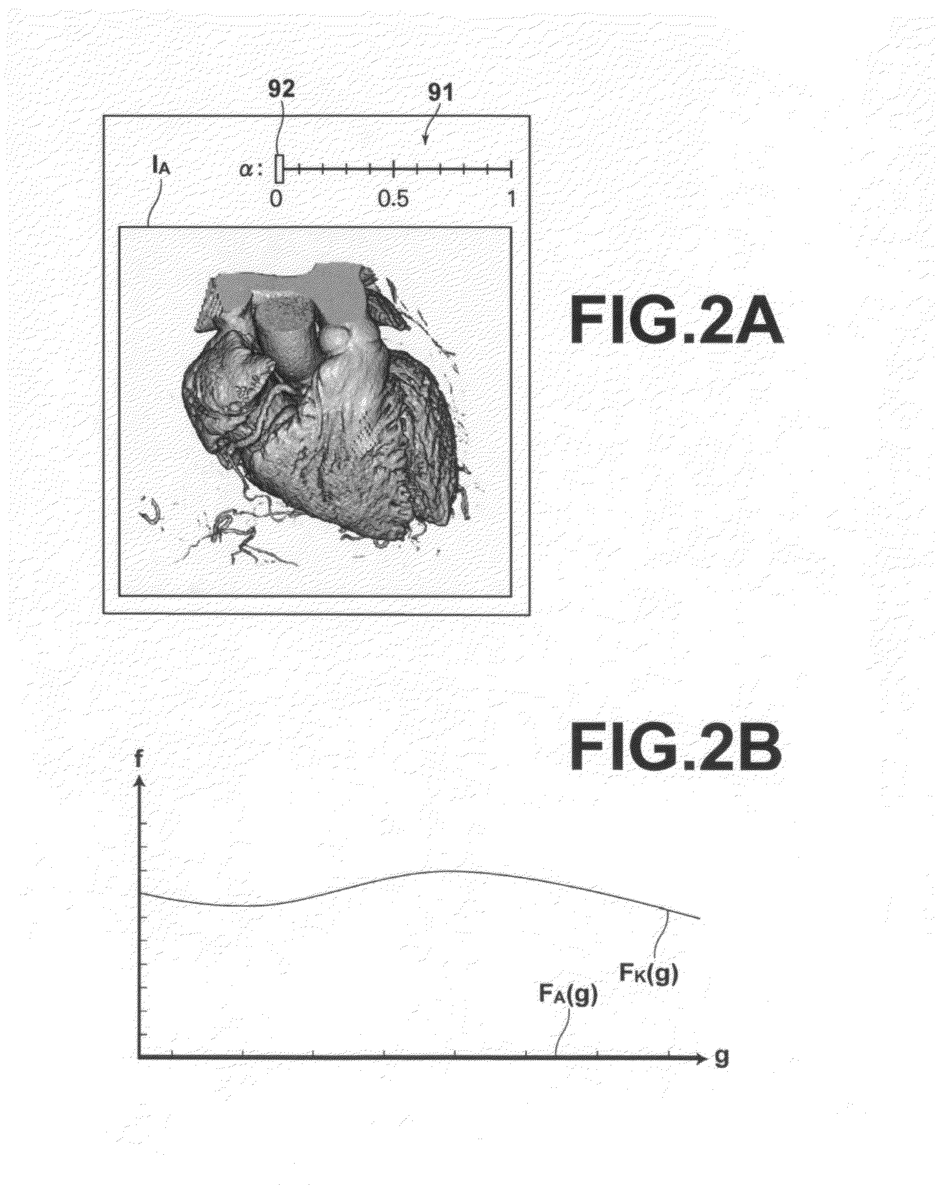
[0030]For example, when generating a projection image that changes from a pseudo three-dimensional image IA generated under the condition of setting function FA(g)=0.0 to a pseudo three-dimensional image IB generated under the condition of setting function FB(g)=1.0 by volume rendering with four search points set along a visual line, if the opacity level determination is made by Formula (1) above using the function t(α) defined by Formula (2) below, graphs 81a (x=2) and 82a (x=3) of the output pixel value C with respect to the changing phase α become closer to linear in comparison with graph 71a of the conventional technology, as shown in FIG. 5. Further, when generating a projection image that changes from a pseudo three-dimensional image IA generated under the condition of setting function FA(g)=1.0 to a pseudo three-dimensional image IB generated under the condition of setting function FB(g)=0.0, if the opacity level determination is made by Formula (1) above using the function t(α) defined by Formula (2) below, graphs 81b (x=2) and 82b (x=3) of the output pixel value C with respect to the changing phase α become closer to linear in comparison with graph 71b of the conventional technology, as shown in FIG. 6. This allows an intermediate image which appears to change substantially linearly with a linear change in the changing phase to be generated.

Problems solved by technology

In this way, the conventional technology described above has a problem that it can not obtain an intermediate image which changes linearly from one to the other of projection images only by linearly changing the changing phase α.

Method used


Image

  • Intermediate image generation method, apparatus, and program
  • Intermediate image generation method, apparatus, and program
  • Intermediate image generation method, apparatus, and program

Examples


Embodiment Construction

[0042]Hereinafter, an embodiment of the present invention will be described with reference to the accompanying drawings.

[0043]FIG. 7 is a hardware configuration diagram of a three-dimensional medical image processing system according to an embodiment of the present invention, illustrating an overview thereof. As shown in FIG. 7, the system includes modality 1, image storage server 2, and image processing workstation 3 communicatably linked to each other via network 9.

[0044]Modality 1 is a system for obtaining a three-dimension medical image V (three-dimensional image) representing a test body and more specifically, it is a CT system, an MRI system, an ultrasonic diagnostic system, or the like.

[0045]Image storage server 2 is a computer for storing in a database and managing the three-dimensional medical image V obtained by modality 1 and a medical image generated through image processing performed in image processing workstation 3, and includes a large capacity external memory unit a...


PUM


Abstract

When generating an intermediate image which is an image in the middle of changing from one to the other of two pseudo three-dimensional images generated by ray casting a three-dimensional image from an arbitrary viewpoint under two different opacity level setting conditions, determining an opacity level setting condition by determining an opacity level to be allocated according to each pixel value such that a variation in the opacity level for a change in a changing phase of the intermediate image become smaller as the changing phase approaches closer to a pseudo three-dimensional image generated under either one of the two different opacity level setting conditions in which a smaller value is allocated as the opacity level to be allocated according to each pixel value, and generating an intermediate image by ray casting the three-dimensional image from an arbitrary viewpoint under the determined opacity level setting condition.

Description

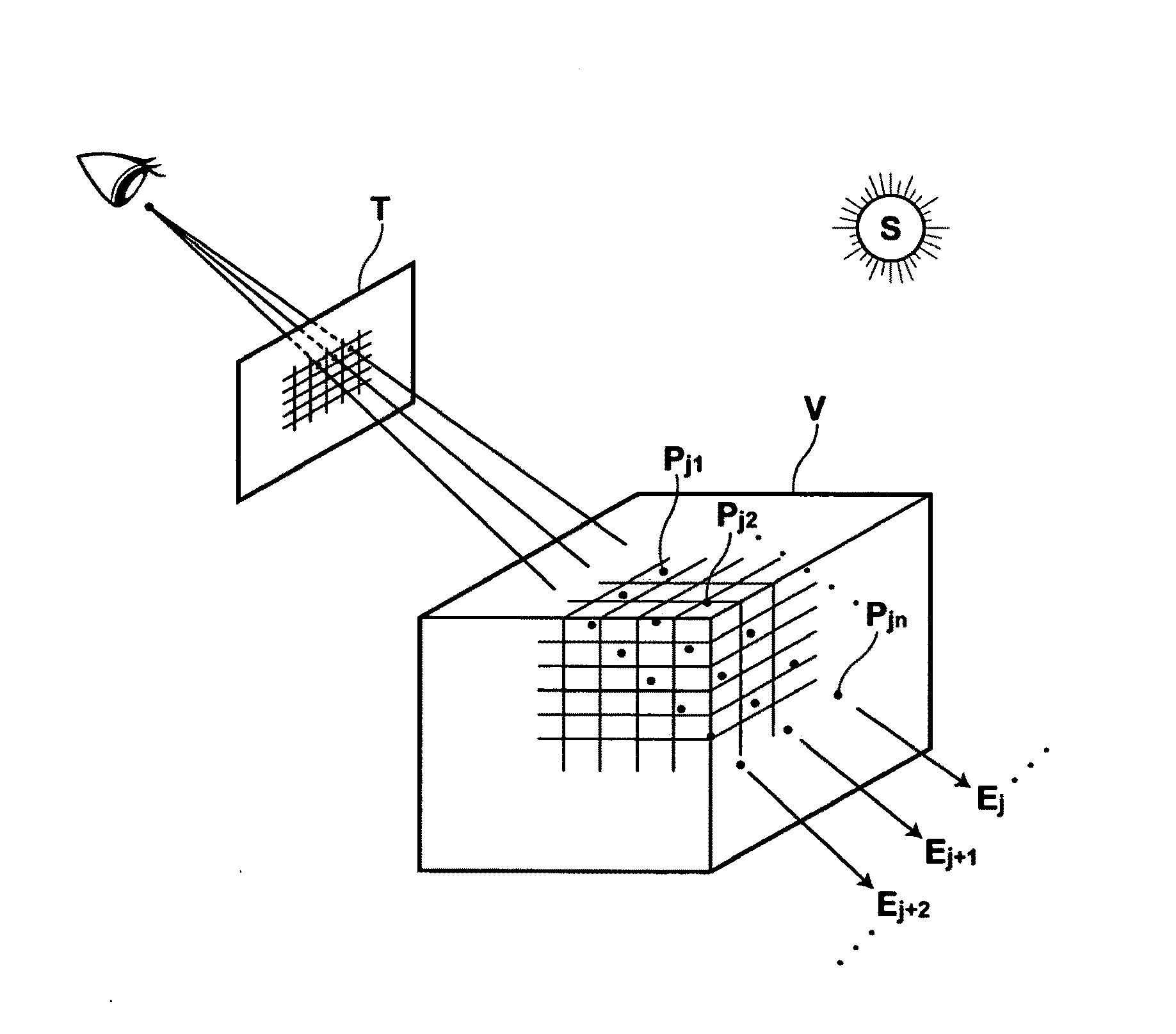
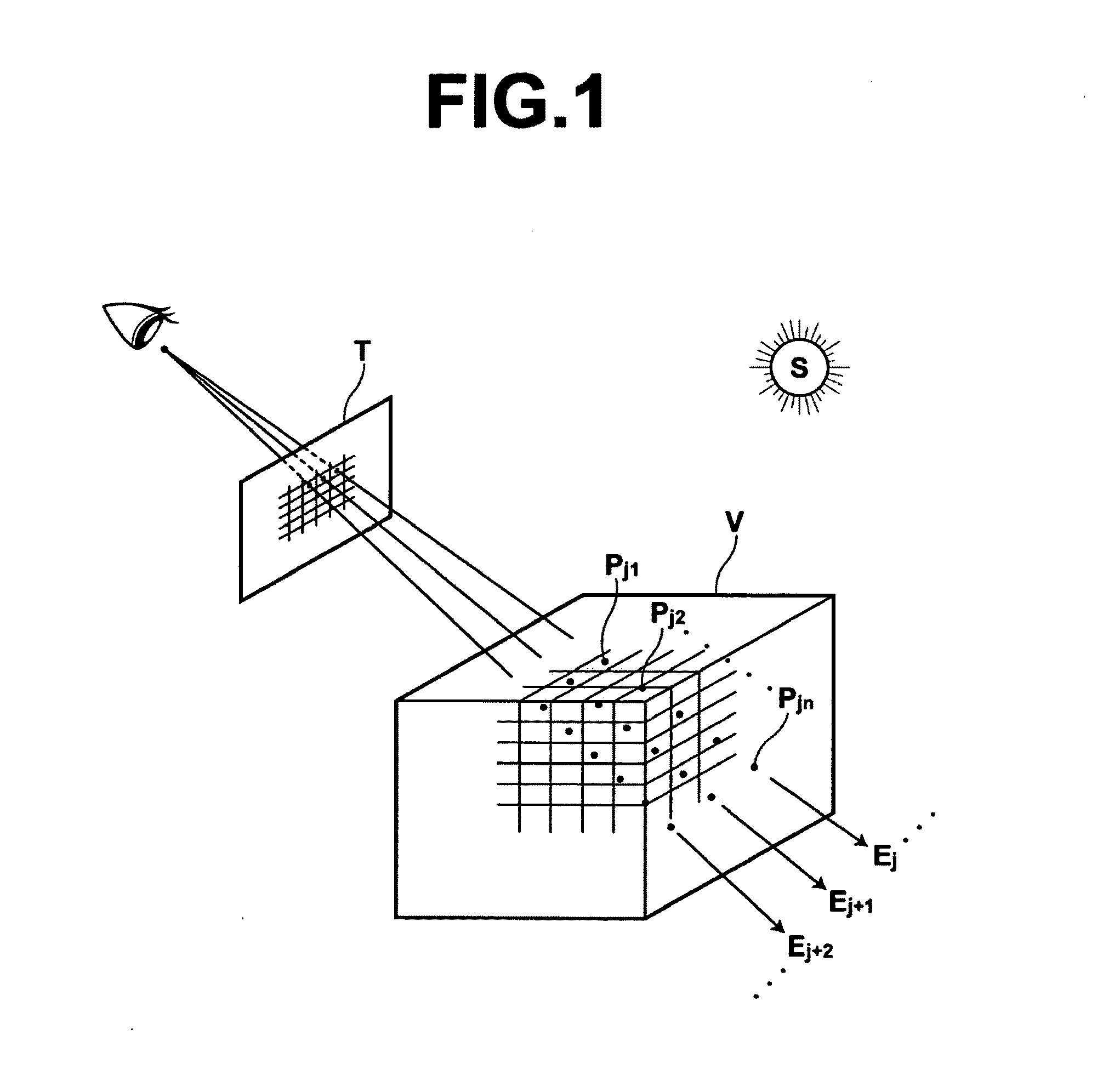
BACKGROUND OF THE INVENTION[0001]1. Technical Field[0002]The present invention relates to an intermediate image generation method, apparatus, and program for generating an intermediate image which is an image in the middle of changing from one to the other of two pseudo three-dimensional images generated by ray casting a three-dimensional image under two different opacity level setting conditions.[0003]2. Description of the Related Art[0004]In order to facilitate understanding of a three-dimensional structure of a subject, image processing for generating and displaying a pseudo three-dimensional image which is three-dimensional image data of a subject, constituted by multiple two dimensional images obtained by a CT system, an MRI system, an ultrasonic diagnostic system, or the like, is stereoscopically visualized on a two-dimensional plane using computer graphics technologies.[0005]As for the method of generating such pseudo three-dimensional images, a volume rendering method is kno...

Claims


Application Information

Patent Timeline
Patent Type & Authority Applications(United States)
IPC IPC(8): G06T15/50A61B5/00A61B5/055A61B6/03A61B8/00G06T15/00
CPCA61B6/466G06T15/503A61B8/483
Inventor MIYAMOTO, MASAKI
Owner FUJIFILM CORP
Why Eureka
Try Eureka