Heat dissipation structure for LED lamp

Inactive Publication Date: 2011-03-31
WU TSU YAO
View PDF6 Cites 23 Cited by
  • Summary
  • Abstract
  • Description
  • Claims
  • Application Information

AI Technical Summary

Benefits of technology

[0008]In the present invention, the metal layers can be provided on one single side or two opposite sides of the circuit boards to provide increased heat dissipation area.
[0009]In the present invention, the heat radiating member provided beneath the top locatin

Problems solved by technology

However, LEDs in working would produce a large amount of heat, which would adversely affect the service life of the LEDs or even cause burnout of the LEDs.
These large-area aluminum radiating fins prevent the LED l

Method used


Image

  • Heat dissipation structure for LED lamp
  • Heat dissipation structure for LED lamp
  • Heat dissipation structure for LED lamp

Examples


Example

[0017]The present invention will now be described with some preferred embodiments thereof. For the purpose of easy to understand, elements that are the same in the preferred embodiments are denoted by the same reference numerals.

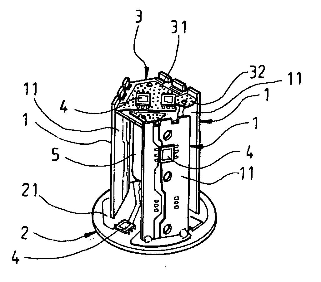
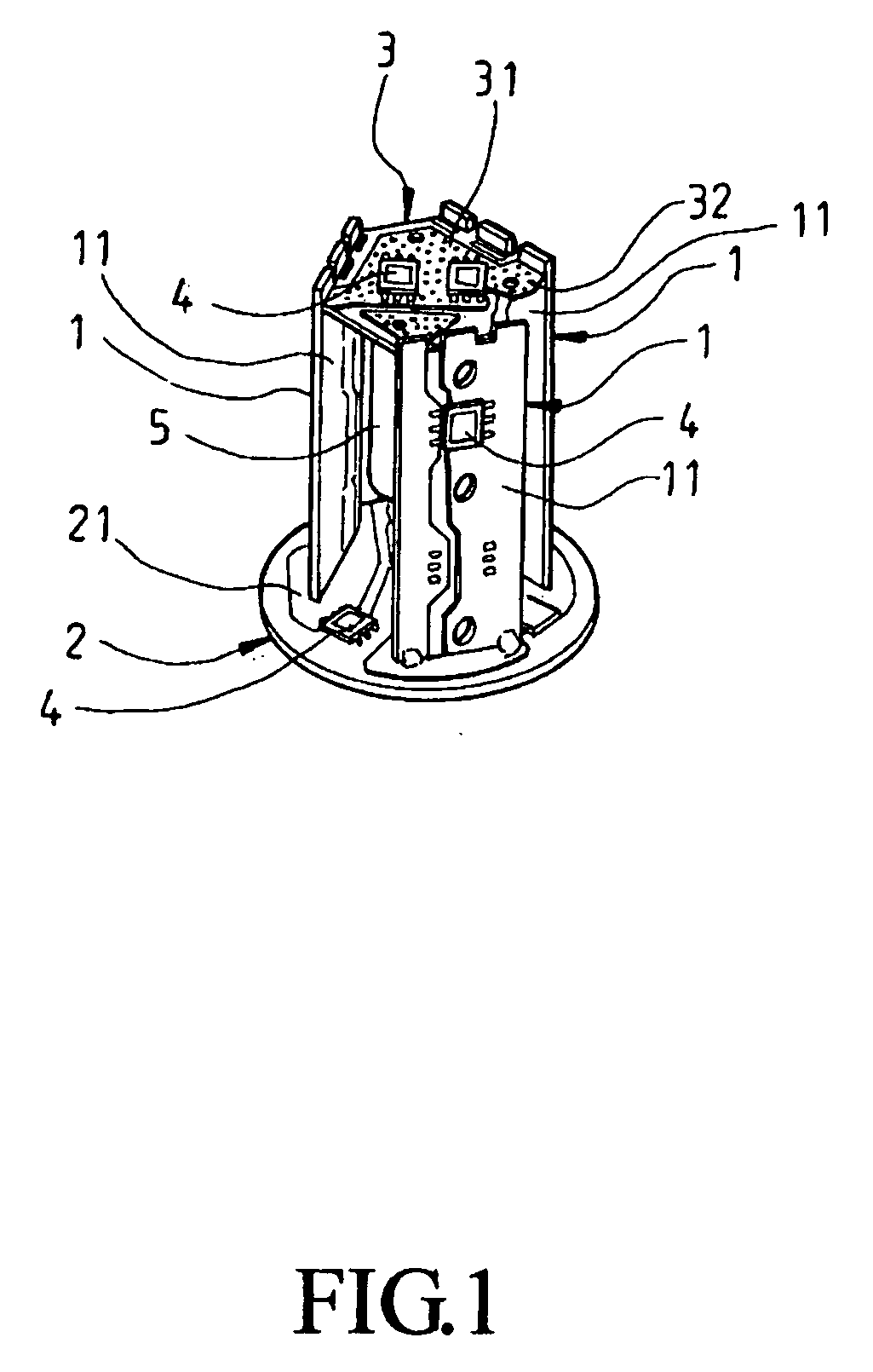
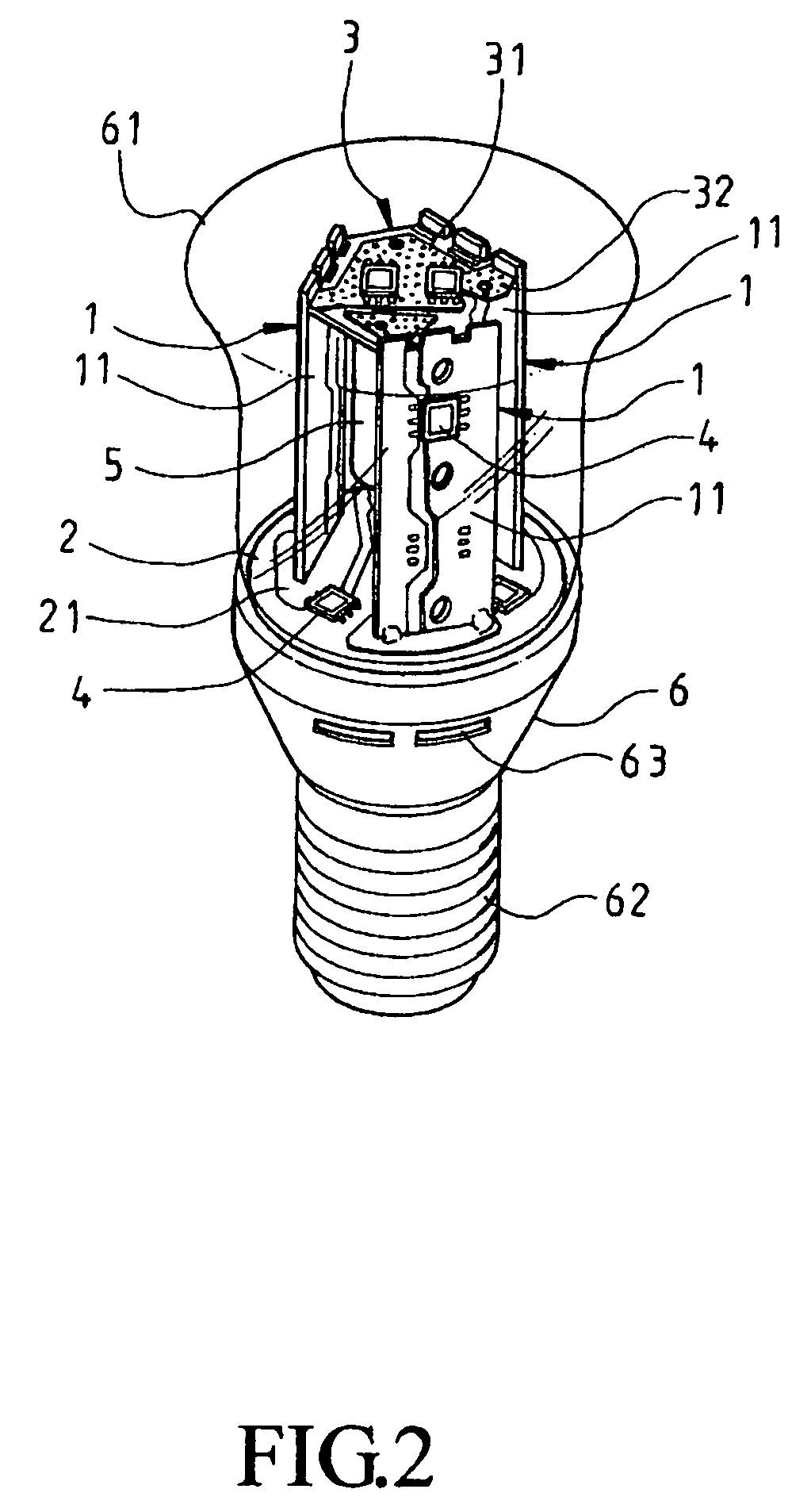
[0018]Please refer to FIG. 1 that is a perspective view of a heat dissipation structure for LED lamp according to a first embodiment of the present invention, and to FIGS. 2 and 3 that are top and bottom perspective view of an LED lamp with the heat dissipation structure of FIG. 1. As shown, the heat dissipation structure for LED lamp in the first embodiment includes one or more mounting plates 1, a bottom locating plate 2, into which lower ends of the one or more mounting plates 1 are inserted, a top locating plate 3 connected to upper ends of the one or more mounting plates 1, and a heat radiating member 5.

[0019]The one or more mounting plates 1 each are provided with a metal layer 11. A plurality of LEDs 4 is welded at respective leads to the metal layers...


PUM


Abstract

A heat dissipation structure for LED lamp includes at least one mounting plate connected to and between a top and a bottom locating plate, and a roll-shaped heat radiating member arranged beneath the top locating plate. The mounting plate and the top and bottom locating plates each are provided with a metal layer, to which LEDs are welded. When the heat dissipation structure is assembled to a lamp holder to form an LED lamp and the LEDs are lightened, heat produced by the LEDs is radiated from the metal layers and the heat radiating member, which together provide a large heat radiating area; meanwhile, perforations on the top locating plate allow convection of air in the LED lamp, and openings provided on the lamp holder allow exchange of air inside and outside the LED lamp, allowing the LED lamp to have reduced volume and increased heat dissipation efficiency.

Description

FIELD OF THE INVENTION[0001]The present invention relates to a heat dissipation structure for LED lamp, and more particularly to an LED lamp heat dissipation structure that has simple structure and small volume to enable the LED lamp to have reduced volume, good heat dissipation effect, and lowered manufacturing cost.BACKGROUND OF THE INVENTION[0002]The light-emitting-diode (LED) lamp, due to its low power consumption and high brightness, has been widely developed and applied to various kinds of products in recent years. However, LEDs in working would produce a large amount of heat, which would adversely affect the service life of the LEDs or even cause burnout of the LEDs. Therefore, most of the conventional LED lamps are provided with a heat dissipation structure to dissipate the heat produced by the working LEDs, so as to maintain the LEDs in normal operation. Conventional heat dissipation structure for LED lamp often includes large-area aluminum radiating fins to dissipate the l...

Claims


Application Information

Patent Timeline
IPC IPC(8): F21V29/00F21V21/00
CPCF21K9/135F21V29/004F21Y2101/02F21V29/83F21V29/20F21V29/74F21V29/78F21V3/02F21K9/232F21Y2115/10F21Y2107/00F21V29/507
Inventor WU, TSU-YAO
Owner WU TSU YAO
Why Eureka
Try Eureka