
Radiation imaging apparatus, radiation imaging method, radiation image processing apparatus, radiation image processing method, and computer-readable storage medium

a radiation imaging and image processing technology, applied in electrical devices, medical science, diagnostics, etc., can solve the problems of difficult to obtain the desired observation image, partly lost image data detected by the quadrangular flat panel detector,

Active Publication Date: 2011-03-31
CANON KK
View PDF0 Cites 5 Cited by
  • Summary
  • Abstract
  • Description
  • Claims
  • Application Information

AI Technical Summary

Benefits of technology

[0018]According to the present invention, it is possible to display the radiation image captured by using the quadrangular flat panel detector in a display form corresponding to each purpose of imaging by controlling the display form of an image in accordance with each purpose of imaging in the imaging mode of storing images and the imaging mode of storing no image.

Problems solved by technology

However, the radiation imaging apparatus using the above FPD has the following problems.
This occurs when, for example, the relative positional relationship between the object and the quadrangular flat panel detector has an error or the vertical and horizontal directions of the quadrangular flat panel detector do not match those of the display device.
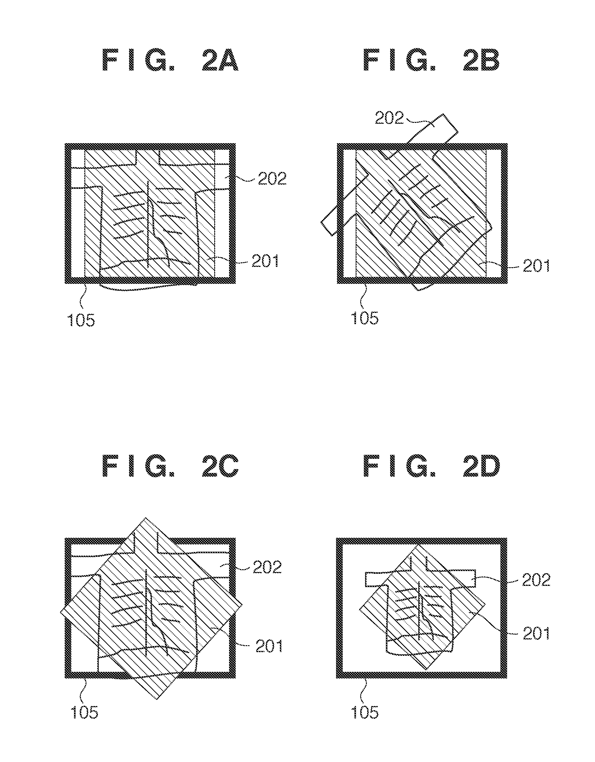
That is, there is a possibility that the image data detected by the quadrangular flat panel detector may be partly lost by rotating operation.
For this reason, setting the same conditions for deciding an image display form such as rotational display, enlarged / reduced display, panning display (display with movement of image center), or the like makes it difficult to obtain a desired observation image.

Method used


Image

  • Radiation imaging apparatus, radiation imaging method, radiation image processing apparatus, radiation image processing method, and computer-readable storage medium
  • Radiation imaging apparatus, radiation imaging method, radiation image processing apparatus, radiation image processing method, and computer-readable storage medium
  • Radiation imaging apparatus, radiation imaging method, radiation image processing apparatus, radiation image processing method, and computer-readable storage medium

Examples


first embodiment

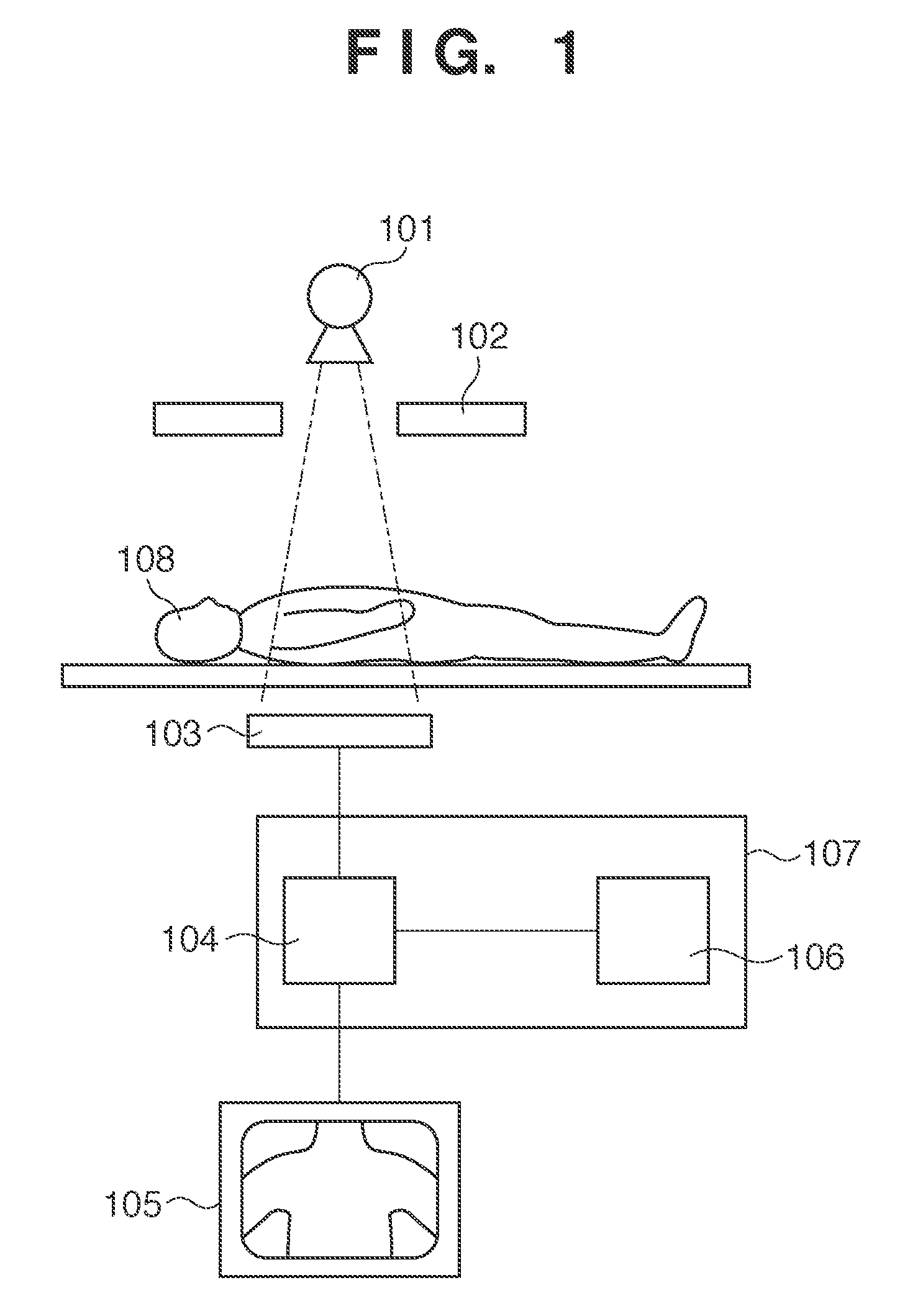
[0026]The schematic arrangement of a radiation imaging apparatus using an FPD according to the present invention will be described with reference to FIG. 1. This apparatus irradiates an object 108 with the radiation emitted from a radiation tube 101 through a radiation stop 102. The apparatus then detects the radiation transmitted through the object 108 through a detector unit 103, and converts the radiation into an image signal. The apparatus is configured to process the converted image signal by using an image processing unit 104 and display the resultant data as an image on a display device 105. The radiation with which the object 108 is irradiated passes through the radiation stop 102 to irradiate only a predetermined range necessary for imaging. The detector unit 103 converts the radiation transmitted through the object 108 into an optical image of visible light using a phosphor in the detector unit 103, and then converts the optical image into an image signal. The image proces...

second embodiment

[0046]In step S505 in the first embodiment, enlargement / reduction conditions are kept the same as those for fit display during radiation irradiation in the mode of storing no radiation image. In contrast, the second embodiment performs enlargement / reduction processing based on user operation within the range of the number of pixels of an image display region, as shown in FIG. 6D. That is, the apparatus can perform operation in a direction to reduce an image from a fit display state at the start of radiation irradiation. It is possible to perform enlargement processing after reduction until fit display. In addition, reduction processing allows panning processing of an image. It is possible to perform panning processing within the range of the number of pixels of an image display region.

third embodiment

[0047]In the first embodiment, the imaging modes are classified into the mode of storing images and the mode of storing no image. In the third embodiment, imaging modes are classified into a mode of storing no moving image, a mode of storing moving images, and a mode of storing still images. Assume that the processing in steps S505 and S506 in the first embodiment is the following processing.

[0048]In step S505 in the first embodiment, rotation processing conditions at the start of radiation irradiation in the mode of storing no image are the same as the final rotation conditions after previous radiation imaging operation (see FIG. 6A). In contrast to this, in the third embodiment, rotation processing conditions at the start of radiation irradiation are the same as the final rotation conditions after the end of radiation imaging in the previous moving image mode.

[0049]In step S506 in the first embodiment, rotation conditions and enlargement / reduction conditions at the start of radiat...


PUM


Abstract

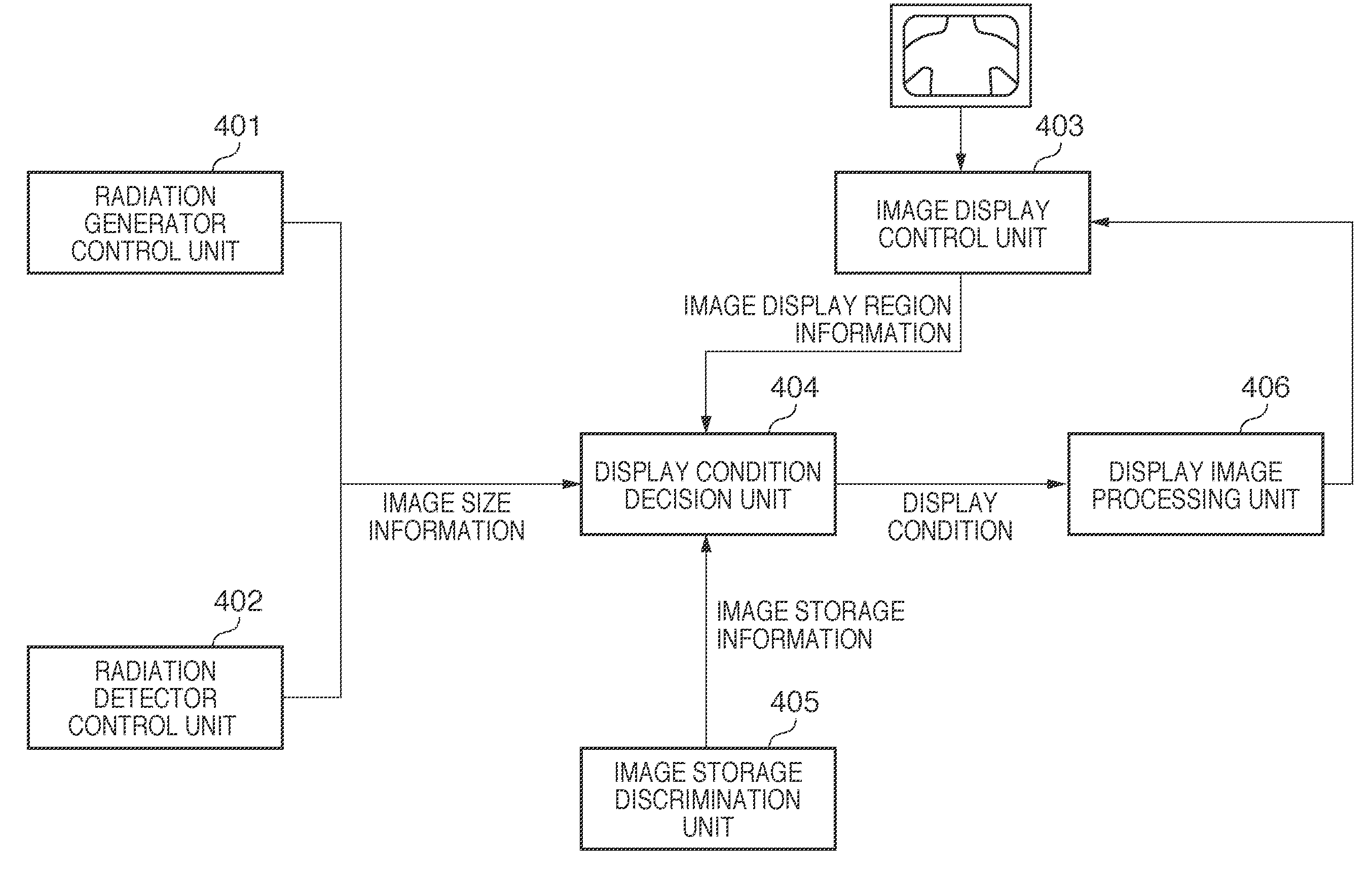
A radiation imaging apparatus includes an imaging unit to capture a radiation image of an object, a discrimination unit to discriminate whether the current imaging mode is a mode of storing radiation images or a mode of storing no radiation image, a first calculation unit to calculate image size information, a second calculation unit to calculate image display region information indicating the size of an image display region, a first decision unit to decide a rotation condition for the rotation of an displayed image, and a second decision unit to decide an enlargement / reduction condition. If discriminated at the start of radiation irradiation that the current mode is the mode of storing no image, the second decision unit decides an enlargement / reduction condition from image size information and image display region information to maximize the ratio of an overall radiation image rotated under the rotation condition decided.

Description

BACKGROUND OF THE INVENTION[0001]1. Field of the Invention[0002]The present invention relates to a radiation imaging apparatus, radiation imaging method, radiation image processing apparatus, radiation image processing method, and computer-readable storage medium.[0003]2. Description of the Related Art[0004]In the field of image diagnosis using radiation imaging apparatuses and more particularly X-ray imaging apparatuses, an image intensifier (to be also referred to as an “I.I.” hereinafter)-TV system has been widely used. Recently, there has been proposed a radiation imaging apparatus using a solid-stage radiation (for example, X-rays) detector with a high resolution which uses an FPD (Flat Panel Detector) in place of an image intensifier. A captured image obtained by an I.I. is circular. In contrast, a radiation imaging apparatus using an FPD allows to increase the effective field of view as compared with an I.I. because the FPD is a quadrangular flat panel detector (having, for e...

Claims


Application Information

Patent Timeline
Patent Type & Authority Applications(United States)
IPC IPC(8): H05G1/64
CPCA61B6/00A61B6/487A61B6/461
Inventor TAKEKOSHI, KOJISAKO, TSUKASA
Owner CANON KK
Learn More