

Combustor
a technology of combustion chamber and combustion chamber, which is applied in the direction of combustion regulation, combustion types, lighting and heating apparatus, etc., can solve the problems of increasing the amount of nox emissions, and achieve the effect of maintaining combustion stability and reducing nox emissions
- Summary
- Abstract
- Description
- Claims
- Application Information
AI Technical Summary
Benefits of technology
Problems solved by technology
Method used
Image

Examples
embodiment 1
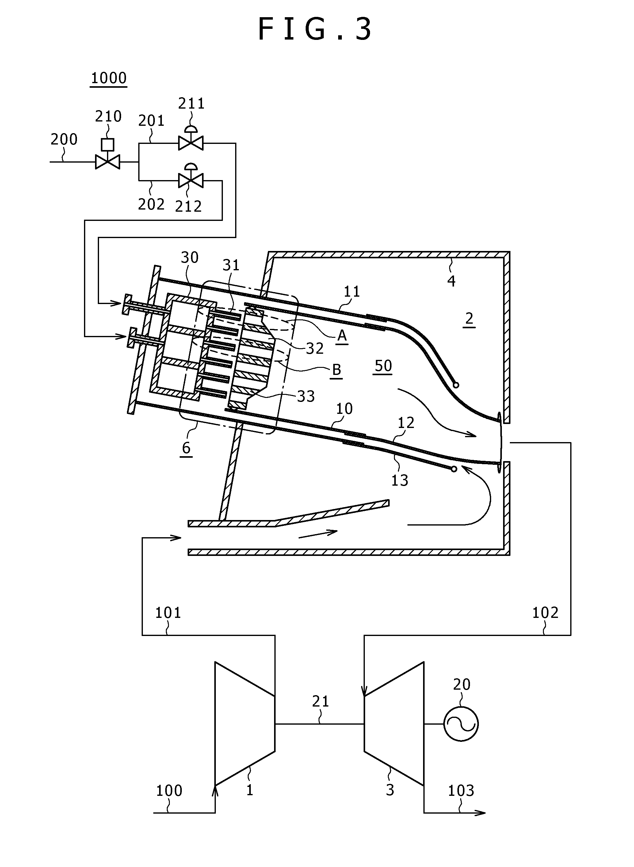
[0038]FIG. 3 illustrates a whole structure of a power generating gas turbine plant 1000.
[0039]A power generating gas turbine in FIG. 3 includes a compressor 1 to generate high pressure air 101 by compressing atmospheric air 100, a combustor 2 to generate high temperature combustion air 102 by burning fuel 200 and high pressure air 101 generated by compressor 1, a turbine 3 driven by high temperature combustion air 102 generated by combustor 102, a power generator 20 rotated by a turbine 3 to generate power, and a shaft 21 to combine the compressor 1, the turbine 3, and the power generator 20.
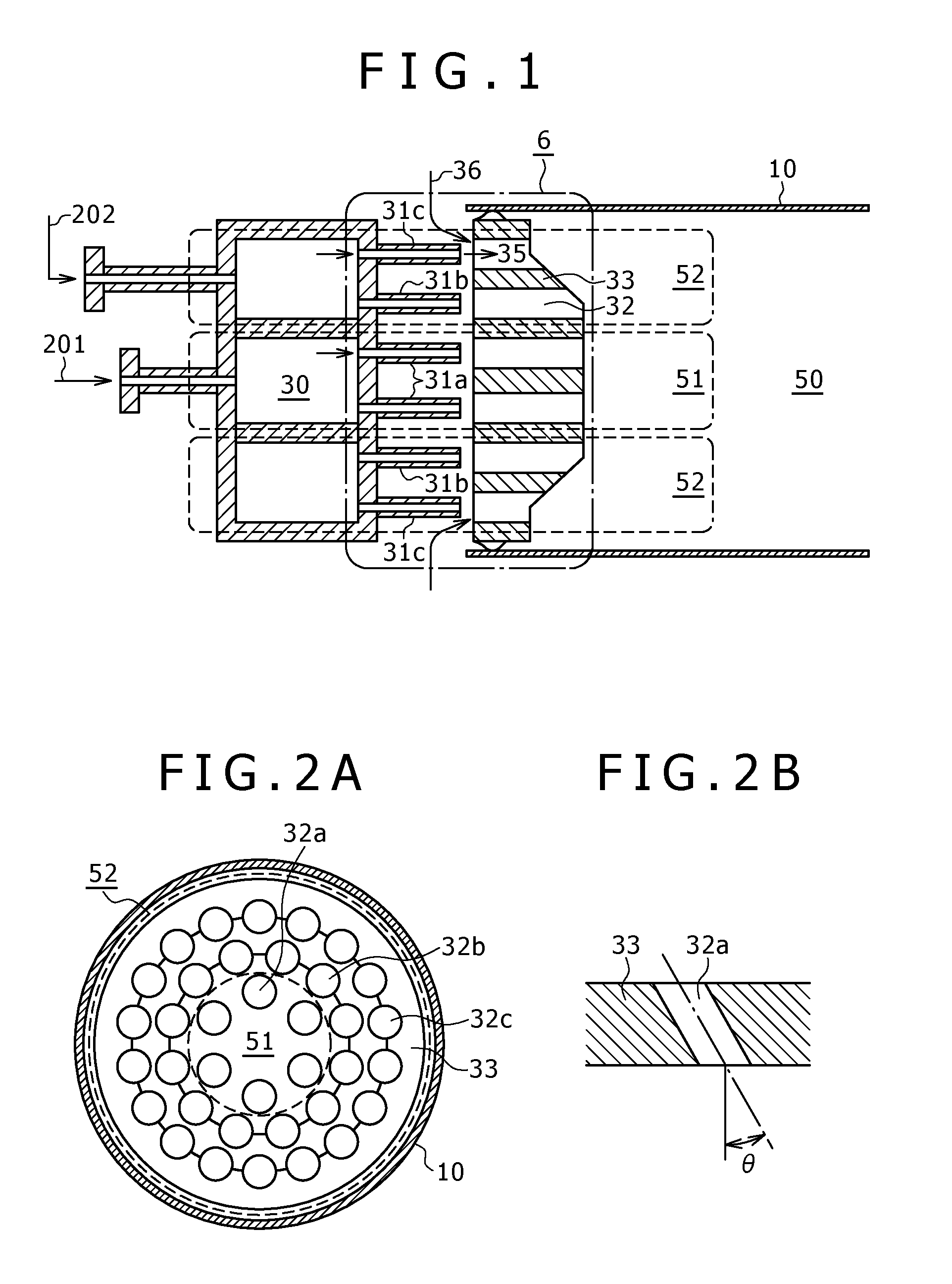
[0040]The combustor 2 is located within a casing 4.
[0041]Combustor 2 has a burner 6 on its head, and a substantially cylindrical combustor liner 10 to separate high pressure air and combustion gas downstream of the burner 6.
[0042]Flow sleeve 11 is disposed on an outer peripheral side of the combustor liner 10, which serves as an outer wall to form a path to let high pressure air flow down. The f...
embodiment 2
[0085]What follows is a description of a gas turbine combustor of a second embodiment, illustrated in FIG. 9.
[0086]As the structure of the combustor of this embodiment is substantially similar to the structure of embodiment 1, only the portions that differ will be discussed.
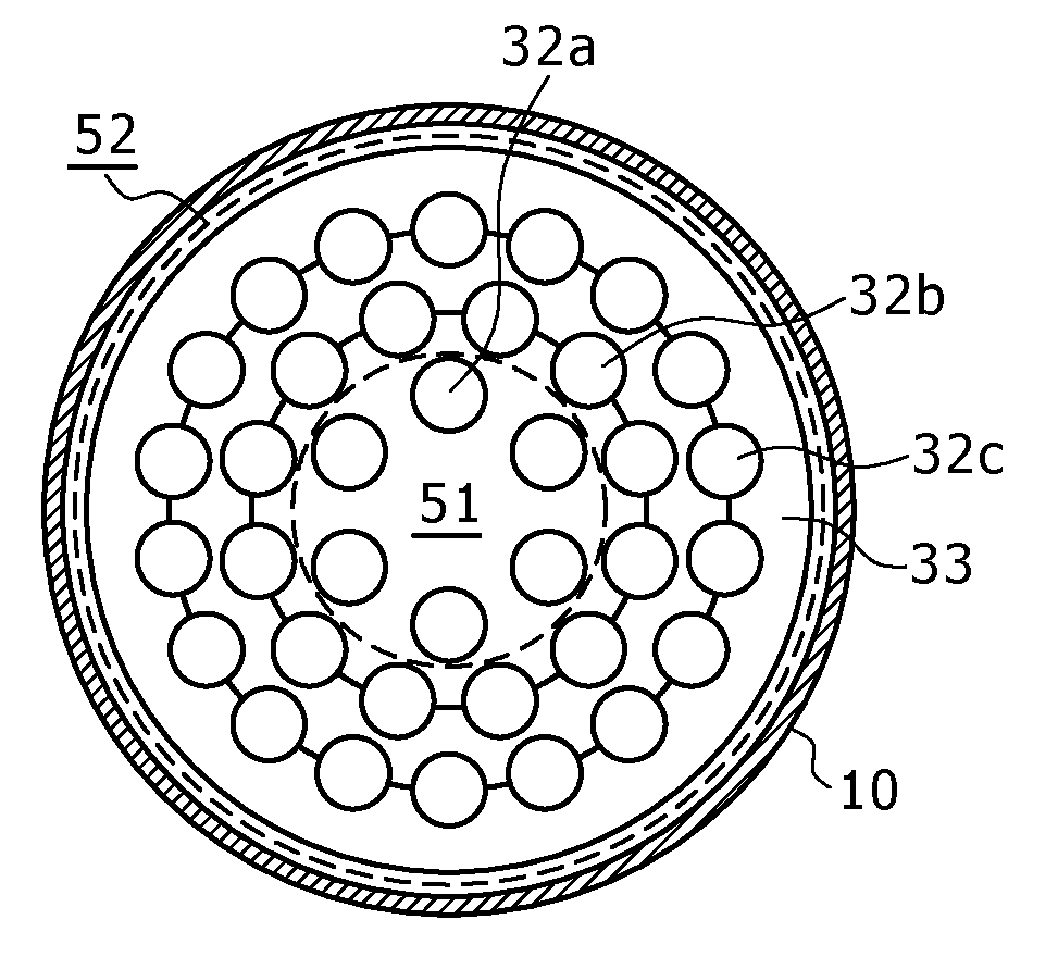
[0087]FIG. 9 is a rough cross section of the enlarged vicinity portion of fuel nozzles 31 and air holes 32, and FIG. 10 is a front view of an air hole plate 33 from a chamber 50 side.
[0088]In this embodiment, thickness of the air hole plate 33 is substantially flat at each position in a radial direction. That is to say, chamber side wall face and fuel nozzle side wall face are in parallel.
[0089]In this embodiment, the thickness of the air hole plate 33 is substantially flat in a radial direction, so internal path lengths of each air hall are also the same between all holes. Therefore, pressure loss caused by air jet 36 passing through an air hole 32 can be constant at any air hole 32 location.
[0090]In addition, i...
embodiment 3
[0095]What follows is a description of a gas turbine combustor of third embodiment with FIG. 11.
[0096]As the structure of the combustor of this embodiment is substantially similar to the structure of embodiment 1, only the portions that differ will be discussed.
[0097]FIG. 11 is a rough cross section of the enlarged vicinity portion of fuel nozzles 31 and air holes 32, and FIG. 12 is a front view of a air hole plate 33 from a chamber 50 side.
[0098]In this embodiment, the structure of inner peripheral coaxial jet nozzle group 51 is the same as embodiment 1. But air holes 32b and 32c in outer peripheral coaxial jet nozzle group 52 have different diameters at each location in an air hole plate 33. That is to say, among third circle air holes 32c in the outer peripheral coaxial jet nozzle group 52, the air holes 32c that have a longer distance from second circle air holes have a larger diameter; on the other hand, the air holes 32c that have a shorter distance from second circle air hole...
PUM
 Abstract
Description
Claims
Application Information