Ultrasonic diagnostic apparatus and ultrasonic contrast imaging method
a diagnostic apparatus and ultrasonic technology, applied in the field of ultrasonic diagnostic apparatus and ultrasonic contrast imaging method, can solve the problem that the bandwidth of the reflected echo signal that is far from the phasing frequency will have difficulty in contributing to imaging, and achieve the effect of improving the image quality of an ultrasonic image and reducing the frame ra
- Summary
- Abstract
- Description
- Claims
- Application Information
AI Technical Summary
Benefits of technology
Problems solved by technology
Method used
Image
Examples
first embodiment
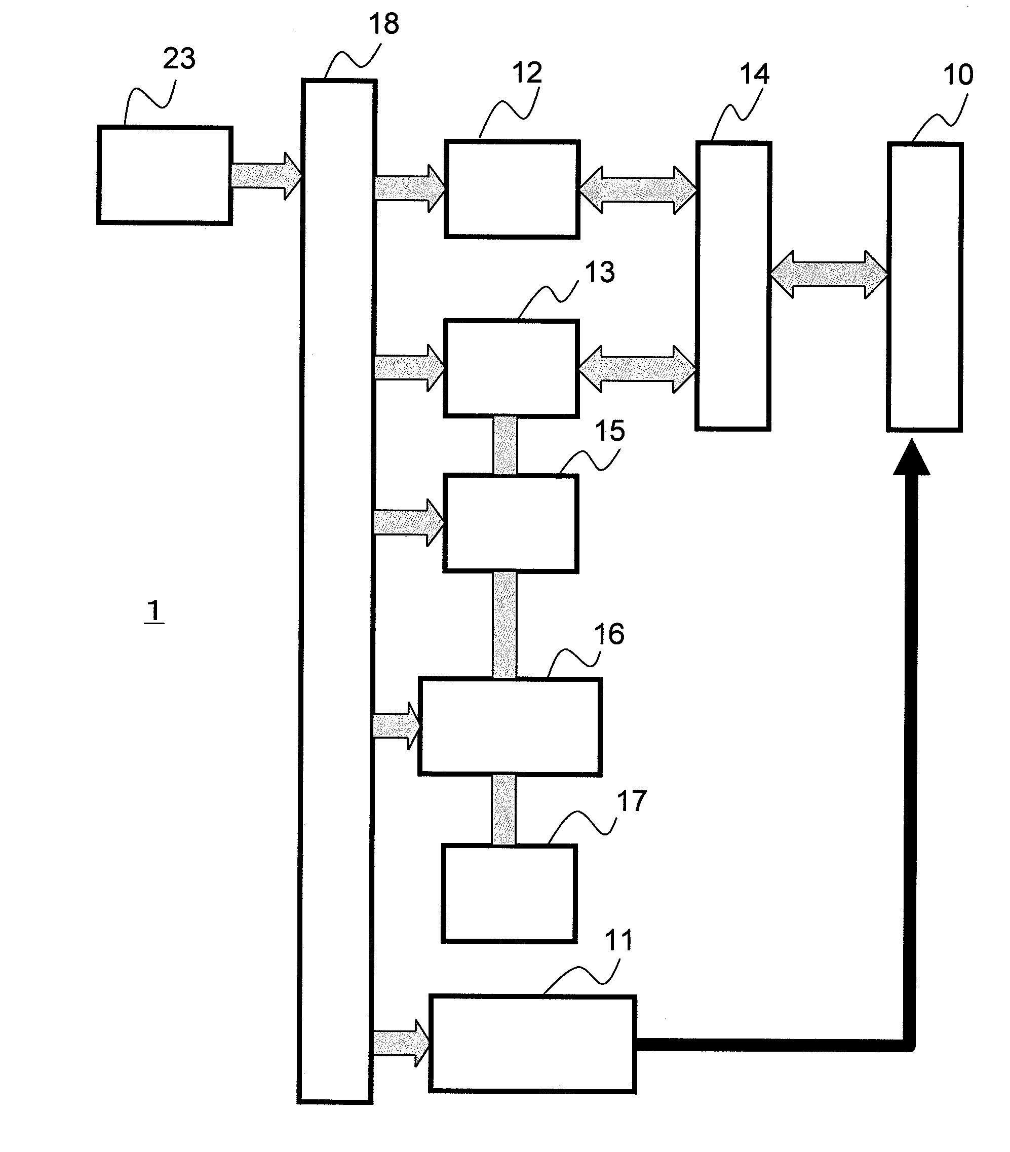
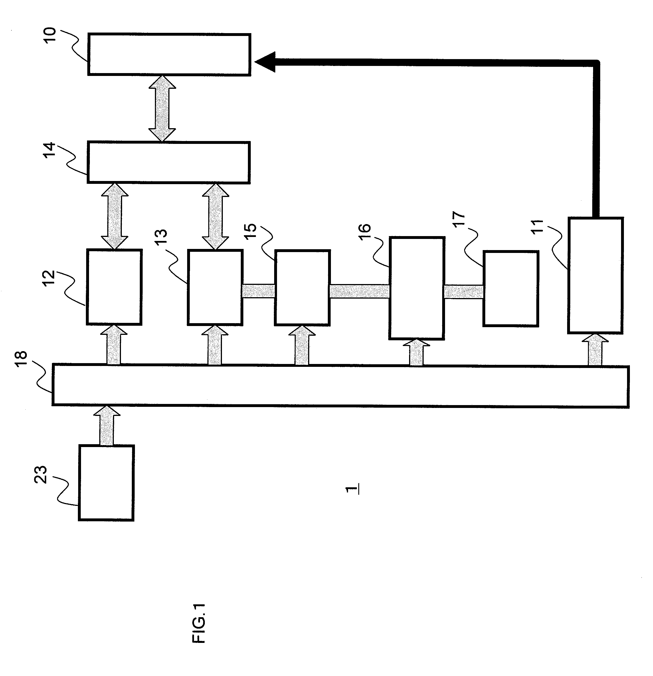
FIG. 1 is a block diagram showing an entire configuration of the ultrasonic diagnostic apparatus in accordance with a first embodiment. An ultrasonic diagnostic apparatus 1 includes: an ultrasonic probe 10 including multiple vibrators; an element selector 11 for selecting an element of the vibrators; a transmitter 12 for transmitting a signal to the ultrasonic probe 10; a reception phasing unit 13 for phasing a signal received from the ultrasonic probe 10; and a transmission / reception separator 14 for switching between the transmitter 12 and the reception phasing unit 13.
Further, the ultrasonic diagnostic apparatus 1 includes: a signal processor 15 for processing a signal from the reception phasing unit 13; a scan converter 16 for scan-converting from ultrasonic scanning to display scanning using a signal from the signal processor 15; a monitor 17, including a CRT, liquid crystal display or the like, for displaying an image data from the scan converter 16; a controller 18 for contro...
second embodiment
Next, a second embodiment of the ultrasonic diagnostic apparatus in accordance with the invention is described. This embodiment is different from the first embodiment only in that a mixture of multiple types of ultrasonic contrast agents is used as an ultrasonic contrast agent to be injected into the object. So, the remaining portion similar to that of the first embodiment is not repeatedly described.
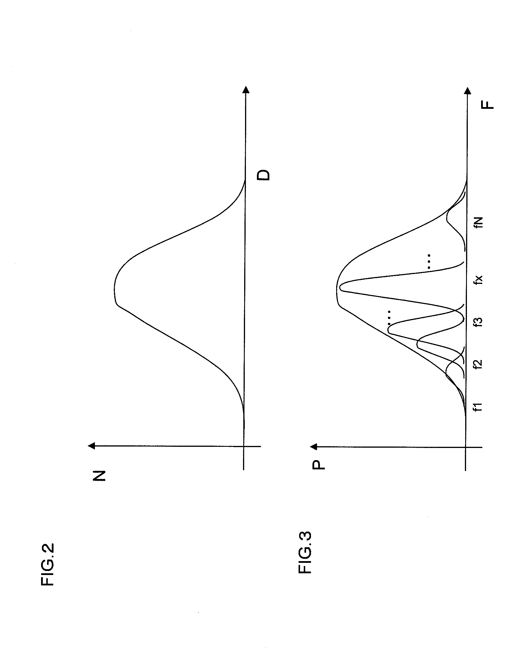
As seen from Eq. 1 above, the resonance frequency of an ultrasonic contrast agent also depends on pressure. This means the resonance frequency depends on the sound pressure of ultrasonic transmission and the hardness of the outer shell forming microbubbles. In other words, the behavior of microbubbles varies depending on sound pressure or mechanical index (MI) or the hardness of the outer shell of the microbubbles.
Accordingly, when an ultrasonic contrast agent includes materials having different outer shells, the resonance frequency is distributed, for example, as shown in FIG. 7. In th...
third embodiment
Next, a third embodiment of the ultrasonic diagnostic apparatus in accordance with the invention is described. This embodiment is different from the first embodiment only in that a mixture of multiple types of ultrasonic contrast agents is used as an ultrasonic contrast agent to be injected into the object, and that difference and sum of frequencies from different resonance frequencies included in reflected echo signals obtained from an area in which the ultrasonic contrast agents exist are included as phasing frequencies. So, the remaining portion similar to that of the first embodiment is not repeatedly described.
In this embodiment, for example, any two frequencies of a signal including multiple resonance frequencies are focused. Then, at least one of the frequency component having the difference of the two frequencies and the frequency component having the sum of the two frequencies is imaged. FIG. 8 shows that reflected echo signals from an area in the object into which two type...
PUM
 Abstract
Description
Claims
Application Information
 - R&D
- Intellectual Property
- Life Sciences
- Materials
- Tech Scout
- Unparalleled Data Quality
- Higher Quality Content
- 60% Fewer Hallucinations
Browse by: Latest US Patents, China's latest patents, Technical Efficacy Thesaurus, Application Domain, Technology Topic, Popular Technical Reports.
© 2025 PatSnap. All rights reserved.Legal|Privacy policy|Modern Slavery Act Transparency Statement|Sitemap|About US| Contact US: help@patsnap.com


