Intraocular iontophoretic device and associated methods

a technology of ionophoretic devices and ocular ion channels, which is applied in the field of ophthalmology, can solve the problems of spatial misalignment between the delivery region and the reservoir, affecting the efficiency of the delivery of active agents, and difficulty in maintaining spatial correspondence with the reservoir, so as to achieve convenient and effective non-invasive delivery and maintain alignmen

Inactive Publication Date: 2011-03-31
ACIONT
View PDF51 Cites 5 Cited by
  • Summary
  • Abstract
  • Description
  • Claims
  • Application Information

AI Technical Summary

Problems solved by technology

When this delivery region of the eye is small, it may be difficult to maintain this spatial correspondence with the reservoir, particularly for delivery devices that are large, bulky, and / or handheld.
In such cases, movements by the subject and / or the individual holding the device may cause spatial misalignment between the delivery region and the reservoir.
Such a misalignment may affect the efficiency of delivery of the active agent.
If the reservoir is shifted because of movement to a non-primed area, the efficiency of active agent delivery may, at least temporarily, decease.
Accordingly, active agent may be more quickly released from two drug depots having an increased surface area as compared to one more concentrated depot, thus reducing the effectiveness of this sustained release mechanism.

Method used


Image

  • Intraocular iontophoretic device and associated methods
  • Intraocular iontophoretic device and associated methods
  • Intraocular iontophoretic device and associated methods

Examples


example 1

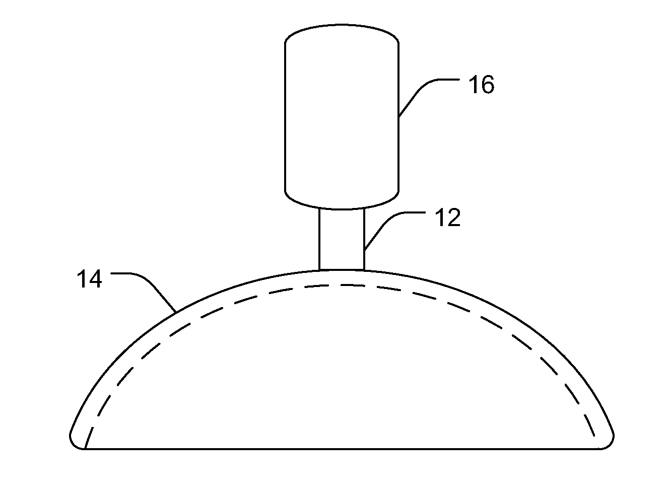
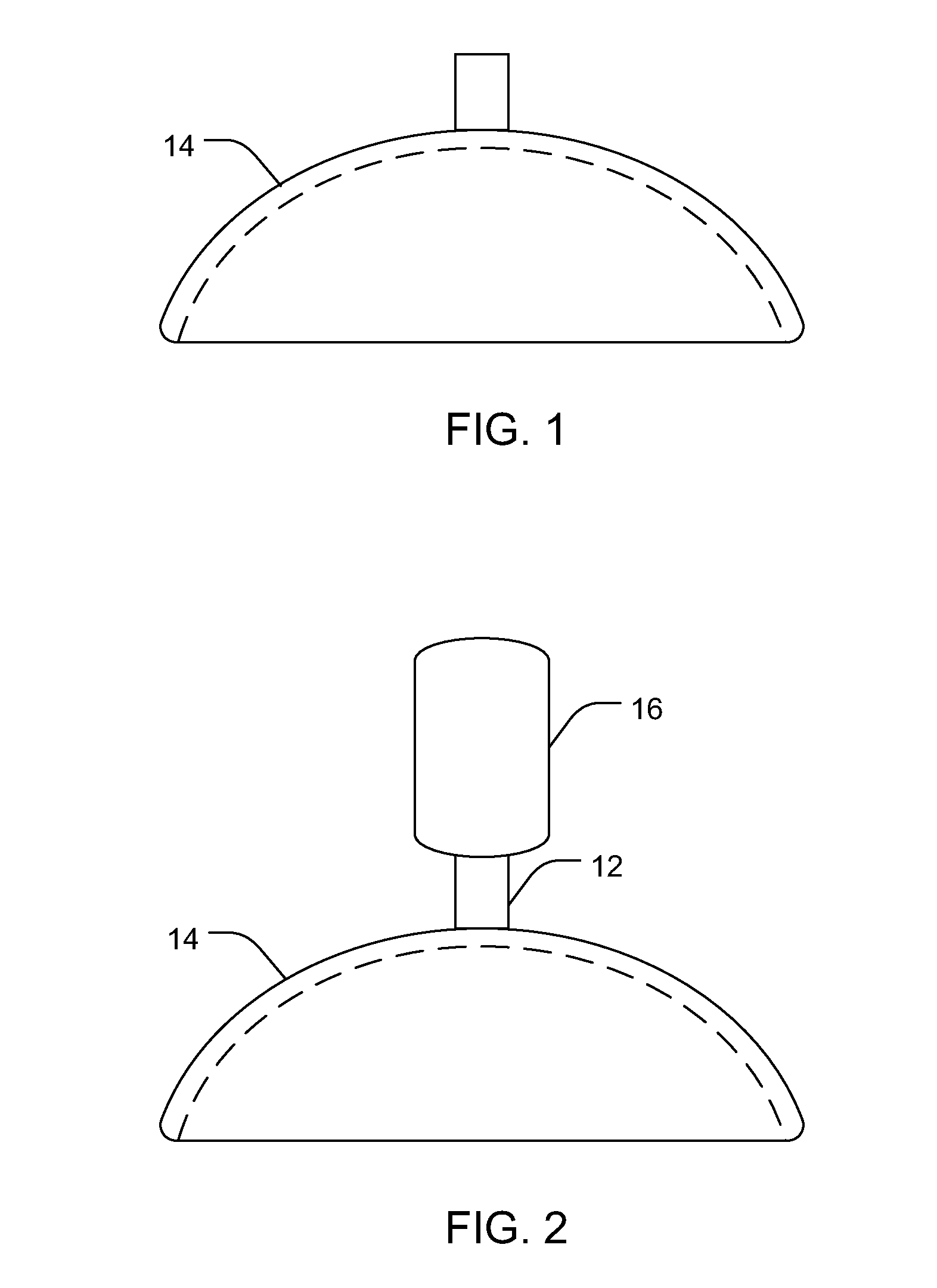
[0094]A handheld ocular iontophoretic device is constructed from a plastic tube, wherein one end is shaped to conform to the eye of a rabbit. An electroplated AgAgCl electrode is positioned in one end of the plastic tube and a hydrogel is inserted into the tube so that one side of the hydrogel contacts the electrode, while the opposite side is configured to contact the eye. The hydrogel has been previously loaded with 1.0M Mn++. The iontophoretic device is coupled to a power source and placed against the surface of an eye of a rabbit, partially within the cul-de-sac in a dorsal location. A return electrode is attached to the ear of the rabbit, and finger pressure is used to seal the device against the eye. 2 mA of current is applied to the iontophoretic device for 20 minutes to deliver the Mn++ from the hydrogel and into the eye. Distribution of the Mn++ within the eye of the rabbit is analyzed using a 3 Tesla Siemens MRI system as is shown in FIG. 7. As can be seen in this figure, ...

example 2

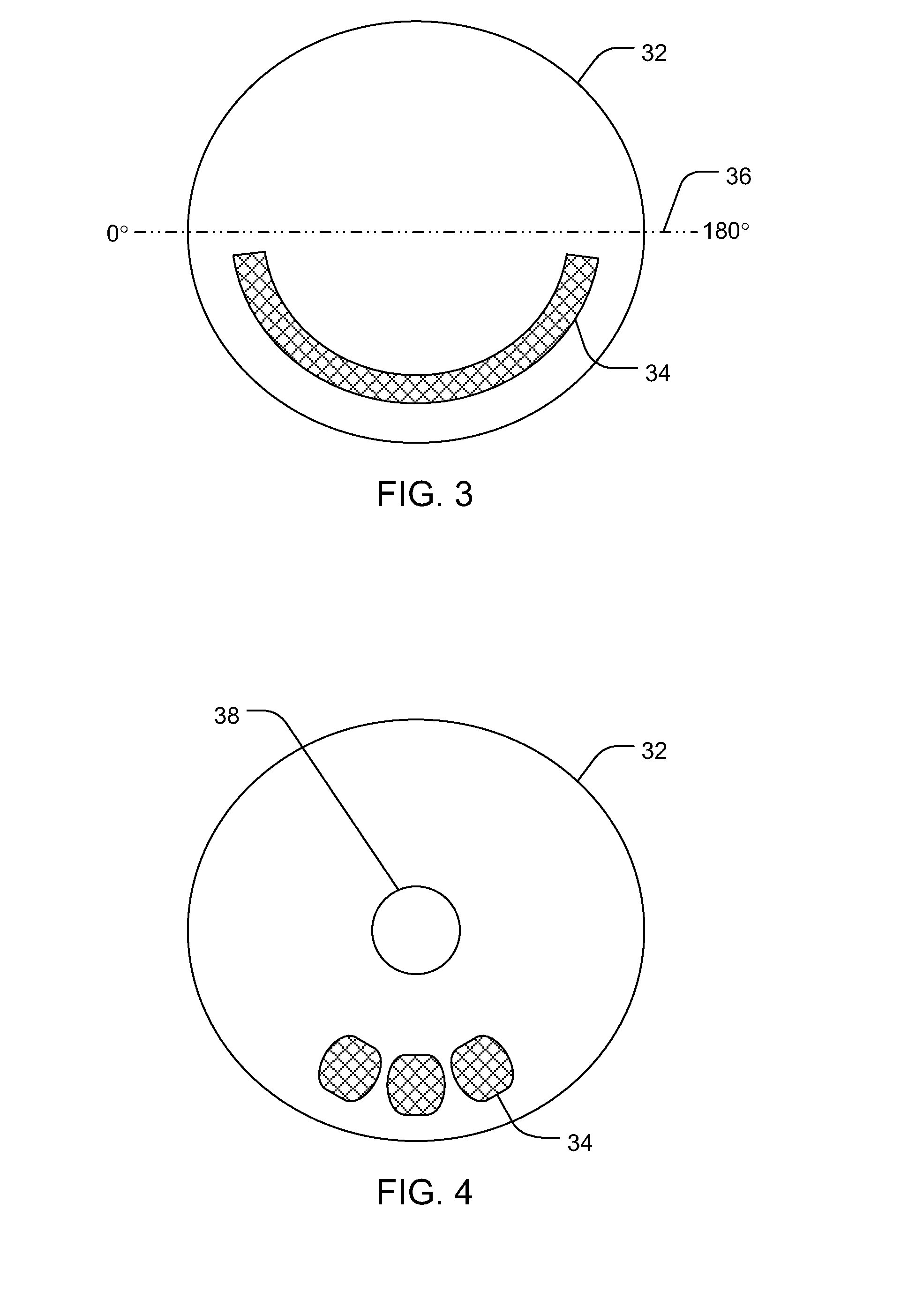
[0095]An iontophoretic scleral lens device is configured to conform to the eye of a rabbit. An electroplated AgAgCl electrode coupled to a 1.0M Mn++ filled hydrogel is located within a reservoir structure along the contact surface of the scleral lens. The iontophoretic device is coupled to a power source and positioned on an eye of a rabbit, such that the reservoir is located partially within the cul-de-sac in a dorsal region of the eye. A return electrode is attached to the ear of the rabbit, and suction is applied to the scleral lens to preclude movement of the lens relative to the eye surface. 3 mA of current is applied to the scleral lens device for 20 minutes to deliver the Mn++ from the hydrogel and into the eye. Distribution of the Mn++ within the eye of the rabbit is analyzed using a 3 Tesla Siemens MRI system as is shown in FIG. 8. As can be seen in this figure, Mn++ ions (white contrast) were delivered primarily into the eye tissues. Additionally, the black region along th...


PUM


Abstract

The present invention includes methods and devices for non-invasively delivering an active agent to the eye of a subject. In one aspect, for example, a device for delivering an active agent to an eye of a subject may include an ocular lens-shaped housing configured to contact a surface of the eye, and a reservoir coupled to the housing and configured to deliver an active agent to the eye, wherein the reservoir is located entirely within a 180 degree section of the housing. In another aspect, the reservoir is located entirely within a 150 degree section of the housing.

Description

PRIORITY DATA[0001]This application is a continuation of U.S. patent application Ser. No. 11 / 867,503, filed Oct. 4, 2007, which is incorporated herein by reference.FIELD OF THE INVENTION[0002]The present invention relates to systems, methods, and devices for the ocular delivery of an active agent into a subject's eye. Accordingly, the present invention involves the fields of chemistry, pharmaceutical sciences, and medicine, particularly ophthalmology.BACKGROUND OF THE INVENTION[0003]Posterior and intermediate eye diseases that require ocular drug delivery to prevent blindness include uveitis, bacterial and fungal endophthalmitis, age-related macular degeneration, viral retinitis, and diabetic retinopathy, among others. For example, the reported incidence of posterior uveitis is more than 100,000 people in the United States. If left untreated, uveitis leads to blindness. It is responsible for about 10 percent of all visual impairment in the U.S. and is the third leading cause of blin...

Claims


Application Information

Patent Timeline
Patent Type & Authority Applications(United States)
IPC IPC(8): A61N1/30A61F9/00
CPCA61F9/0017A61K9/0009A61N1/30A61M2210/0612A61M35/003A61P27/02
Inventor TUITUPOU, ANTHONY L.HIGUCHI, JOHN W.
Owner ACIONT
Why Eureka
Try Eureka