
Insertion device and insertion method of coil

a coil and insertion device technology, applied in the field of insertion devices and coil insertion methods, can solve the problems of critical control of the manipulation of the catheter or the delivery wire, and the skill of the medical treatment based on the catheter, and achieve the effect of favorable accuracy

Inactive Publication Date: 2011-03-31
NTN CORP
View PDF13 Cites 38 Cited by
  • Summary
  • Abstract
  • Description
  • Claims
  • Application Information

AI Technical Summary

Benefits of technology

The present invention relates to an insertion device and method for coil embolization treatment of cerebral aneurysms. The technical effect of the invention is to provide an insertion device that can accurately insert a coil into an aneurysm while avoiding excessive insertion force and maintaining the position of the tip of the catheter in the aneurysm. The invention addresses the problem of requiring skill and manipulation of the catheter and delivery wire in medical treatment based on a catheter. The invention proposes an insertion device that includes a first driving unit moving a catheter into which a delivery wire is inserted, a second driving unit moving the delivery wire, and a control unit controlling the second driving unit so as to insert the delivery wire by a predetermined insertion force. The device can automatically insert the delivery wire without requiring excessive insertion force and maintain the position of the tip of the catheter in the aneurysm. The invention provides an improved method for coil embolization treatment of cerebral aneurysms.

Problems solved by technology

Medical treatment based on a catheter requires skill, and the manipulation of the catheter or delivery wire requires critical control.

Method used


Image

  • Insertion device and insertion method of coil
  • Insertion device and insertion method of coil
  • Insertion device and insertion method of coil

Examples


first embodiment

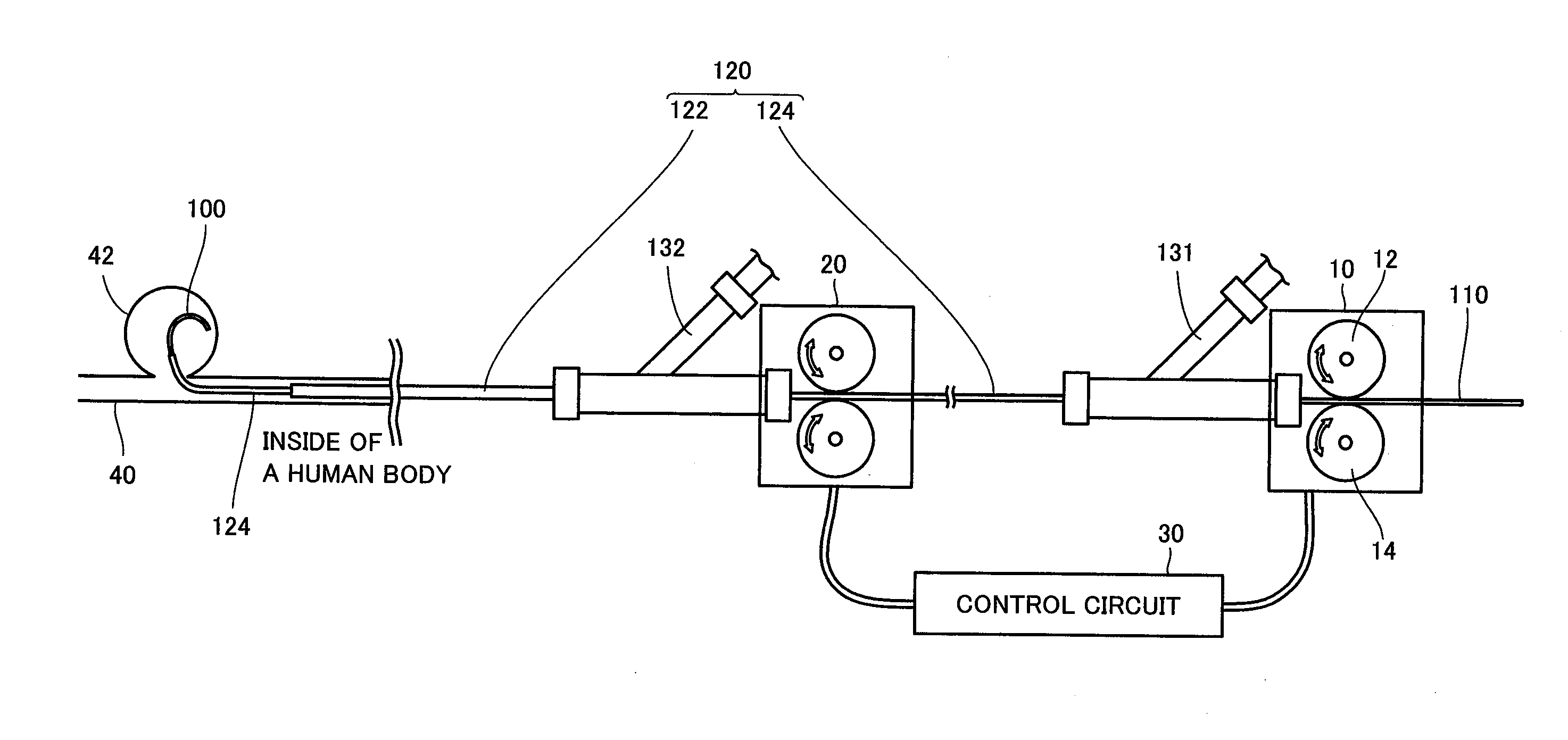
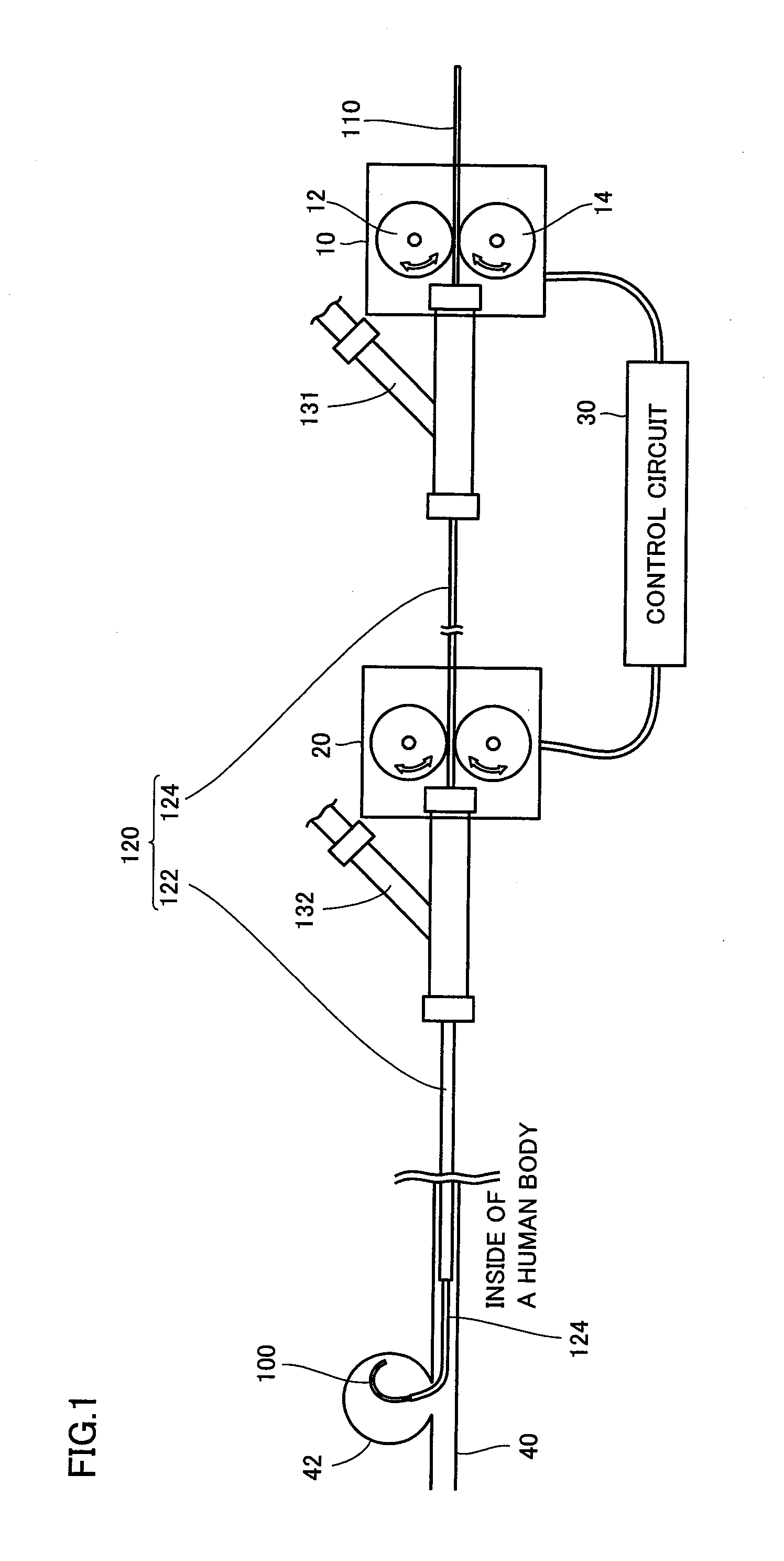
[0040]An insertion device of a coil according to a first embodiment of the present invention will be described hereinafter. As shown in FIG. 1, an insertion device of a coil includes a delivery wire driving unit 10, a secondary catheter driving unit 20, and a control circuit 30.

[0041]By way of example, the present embodiment will be described based on an insertion device as a medical instrument employed in the coil embolization treatment of an aneurysm 42 developed at a blood vessel 40 in the brain. The application of the insertion device is not limited to the coil embolization treatment of an aneurysm 42.

[0042]A platinum coil 100 for coil embolization is attached at the tip of a delivery wire 110. Delivery wire 110 and a catheter 120 are inserted in Y connectors 131 and 132, respectively.

[0043]Catheter 120 includes a primary catheter 122 and a secondary catheter 124. Primary catheter 122 and secondary catheter 124 are hollow. Secondary catheter 124 is inserted in the hollow region ...

second embodiment

[0067]A second embodiment of the present invention will be described hereinafter. The present embodiment differs from the previous first embodiment in that, if delivery wire 110 cannot be inserted into aneurysm 42 even after repeating moving back and advancement of secondary catheter 124 by a predetermined number of times, the distance of moving back and advancement of secondary catheter 124 is increased. The remaining structure is identical to that of the first embodiment set forth above. Therefore, detailed description thereof will not be repeated.

[0068]A control structure of the program executed by control circuit 30 according to the present embodiment will be described hereinafter with reference to FIG. 7. The processes identical to those in the program of the previous first embodiment have the same step number allotted. Therefore, detailed description thereof will not be repeated.

[0069]At S50, control circuit 30 determines whether moving back and advancement of secondary cathet...

third embodiment

[0078]A third embodiment of the present invention will be described hereinafter. The present embodiment differs from the previous first and second embodiments in that delivery wire 110 is advanced while secondary catheter 124 is moved back, and delivery wire 110 is moved back while secondary catheter 124 is advanced. The remaining configuration is similar to that of the previous first or second embodiment. Therefore, detailed description thereof will not be repeated.

[0079]A control structure of the program executed by control circuit 30 according to the present embodiment will be described with reference to FIG. 8. The processes identical to those in the program of the previous first embodiment have the same step number allotted. Therefore, detailed description thereof will not be repeated.

[0080]At S60, control circuit 30 controls secondary catheter driving unit 20 and delivery wire driving unit 10 such that secondary catheter 124 is moved back by just a predetermined distance, and ...


PUM


Abstract

An insertion device of a coil includes a delivery wire driving unit, a secondary catheter driving unit, and a control circuit. A platinum coil for coil embolization is attached to the tip of a delivery wire. The delivery wire driving unit is provided in the proximity of the entrance of a Y connector such that the delivery wire is advanced and moved back. The secondary catheter driving unit is provided in the proximity of the entrance of a Y connector such that the secondary catheter is advanced and moved back. The control circuit controls the delivery wire driving unit so as to insert the delivery wire by a predetermined insertion force. If the delivery wire cannot be inserted, the control circuit controls the secondary catheter driving unit such that the secondary catheter is advanced after being moved back, and then controls the delivery wire driving unit so as to insert the delivery wire.

Description

TECHNICAL FIELD[0001]The present invention relates to an insertion device and an insertion method of a coil. Particularly, the present invention relates to the technique of inserting a coil attached to the tip of a delivery wire for embolization treatment of a cerebral aneurysm.BACKGROUND ART[0002]Treatment using a minimally invasive catheter is conventionally carried out. For example, FIG. 12 shows a medical instrument employed in the coil embolization treatment of a cerebral aneurysm that is the cause of subarachnoid bleeding. A platinum coil for coil embolization is attached to the head of a delivery wire. This delivery wire and a catheter are inserted into a Y connector. The catheter is hollow. The delivery wire is inserted in the hollow region of the catheter. The surgeon manipulates the delivery wire and catheter in the proximity of the entrance of the Y connector.[0003]Medical treatment based on a catheter requires skill, and the manipulation of the catheter or delivery wire ...

Claims


Application Information

Patent Timeline
Patent Type & Authority Applications(United States)
IPC IPC(8): A61M29/00
CPCA61B17/12022A61B17/12113A61B17/1214A61B19/22A61B2017/00398A61M25/09041A61B2019/461A61B2019/464A61M25/01A61M25/0105A61M25/0113A61B2017/1205A61B34/70A61B2090/061A61B2090/064A61B5/0048A61B5/0053A61B5/0057
Inventor NAGANO, YOSHITAKANISHIO, YUKIHIROOZAKI, TAKAYOSHI
Owner NTN CORP
Learn More