

Methods and Systems Involving Carbon Sequestration and Engines
a technology of carbon sequestration and power systems, applied in the direction of machines/engines, separation processes, mechanical equipment, etc., can solve the problem of energy consumption of carbon dioxide gas from exhaust gases
- Summary
- Abstract
- Description
- Claims
- Application Information
AI Technical Summary
Problems solved by technology
Method used
Image

Examples
Embodiment Construction
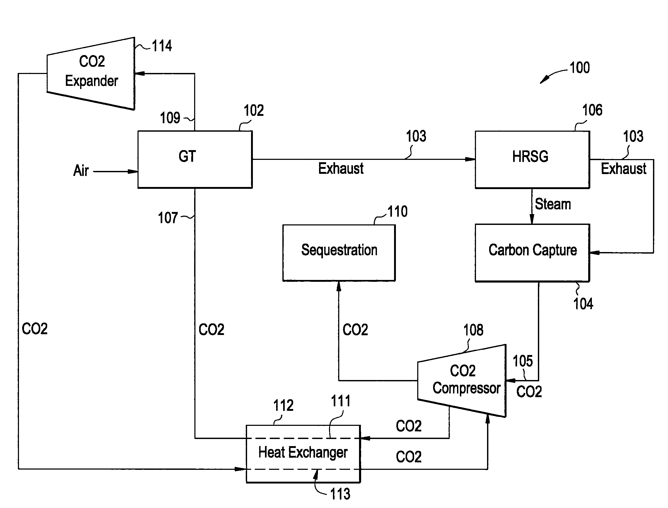
Carbon capture means and sequestration (CCS) is used to remove CO2 from system exhaust gases and store the CO2 in a sequestration location. CCS methods often consume energy, resulting in a loss of system efficiency; for example, post-combustion amine-based removal of CO2 uses energy for solvent regeneration e.g., thermal energy from a heat recovery steam generator or steam turbine extraction, and power used to drive a compressor that compresses the CO2 for sequestration. Gas turbine engines often use pre-combustion compressed air (bleed air) to cool engine components. The use of the bleed air reduces the performance, i.e., output and thermal efficiency, of the gas turbine engine.
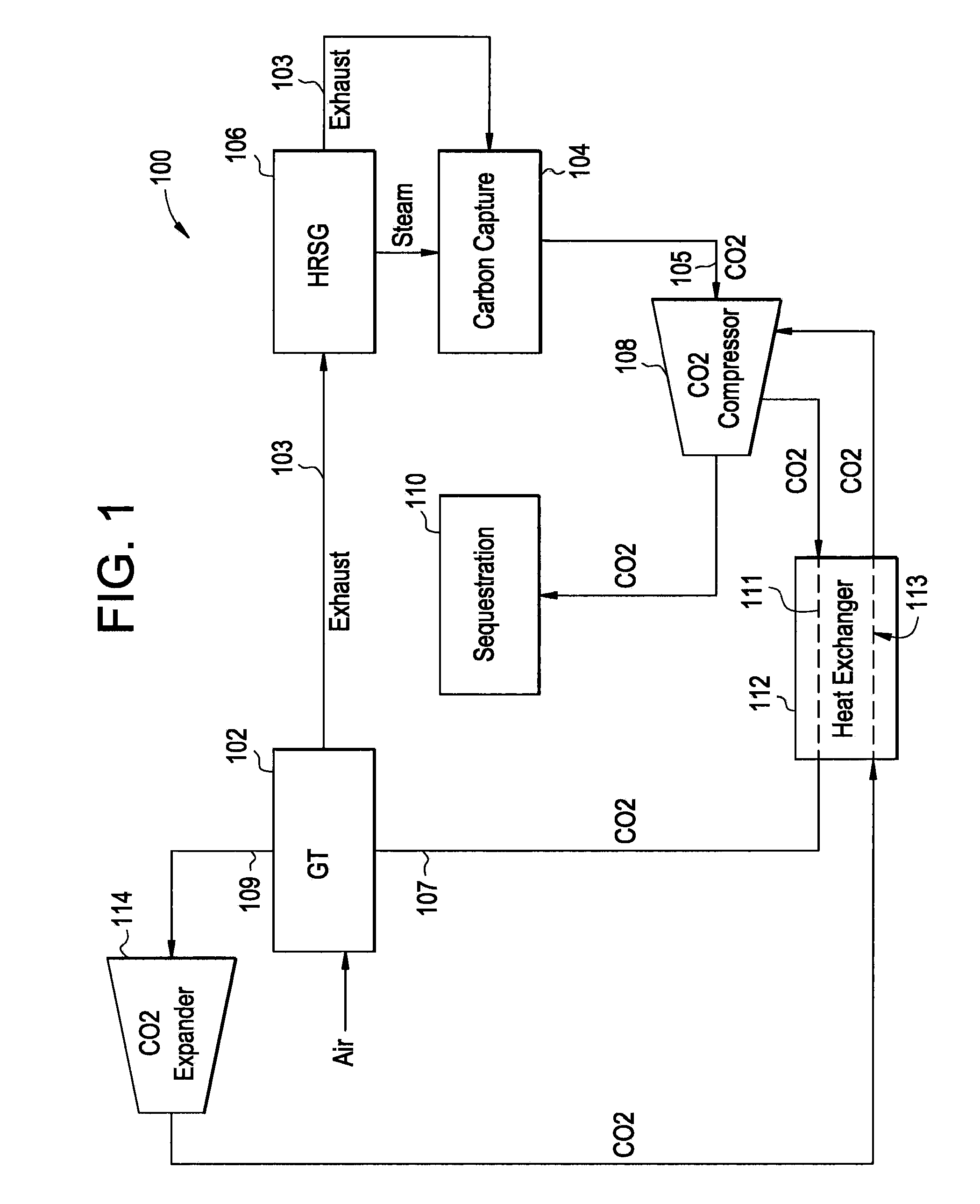
FIG. 1 illustrates an exemplary system and method for increasing the efficiency of a power system that uses CCS. In this regard, the system 100 includes a gas turbine engine 102 that outputs post-combustion exhaust gas 103 to a carbon capture means 104 via a heat recovery steam generator (HRSG) 106. The illu...
PUM
 Abstract
Description
Claims
Application Information