
Pump Valve with Full Elastomeric Contact on Seat

a technology of elastomeric contact and valve seat, which is applied in the direction of functional valve types, machines/engines, liquid fuel engines, etc., can solve the problems of wear on the valve surface, metal fatigue, and non-uniform stresses in the flang

Inactive Publication Date: 2011-04-07
WEIR SPM
View PDF22 Cites 79 Cited by
  • Summary
  • Abstract
  • Description
  • Claims
  • Application Information

AI Technical Summary

Benefits of technology

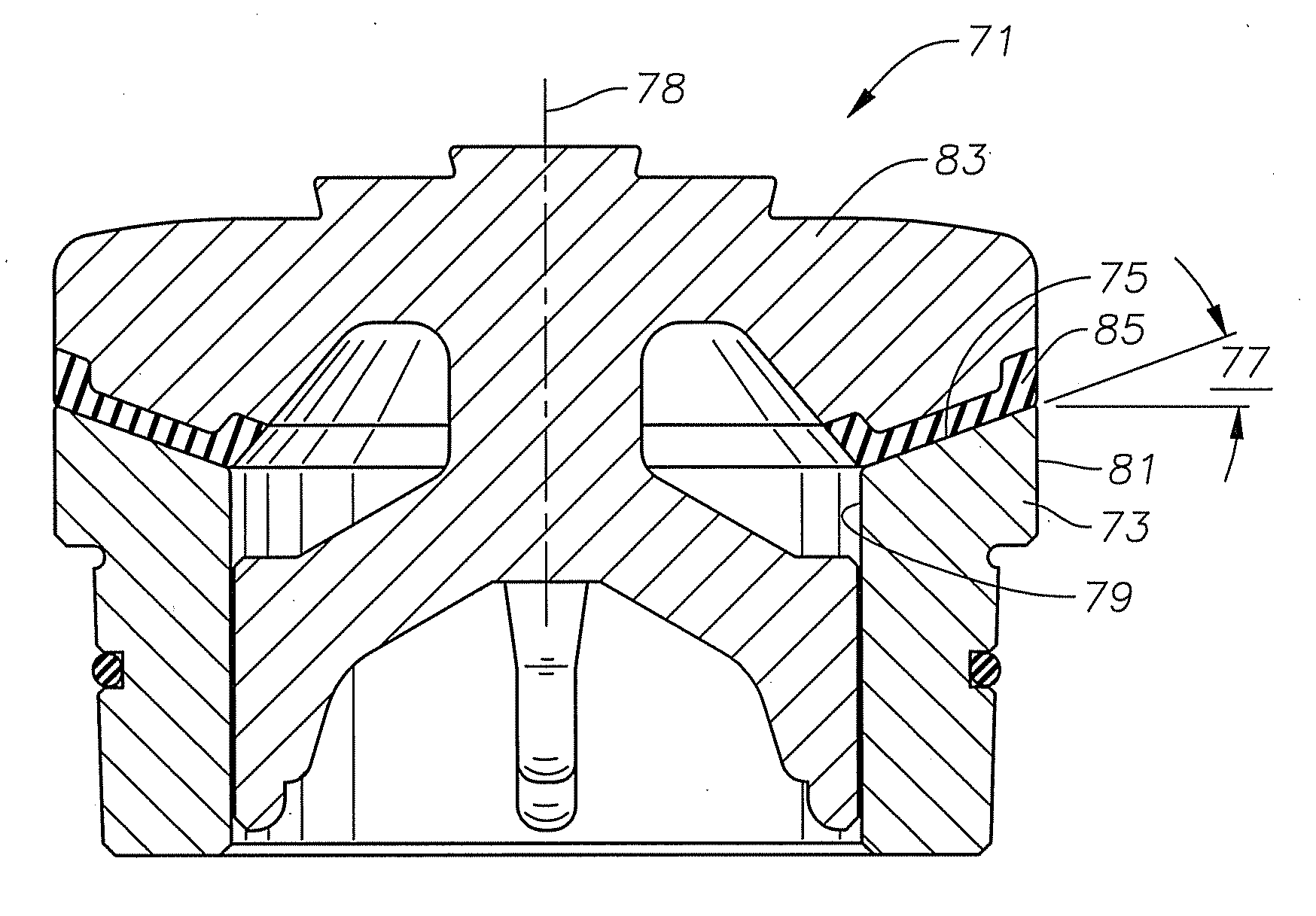
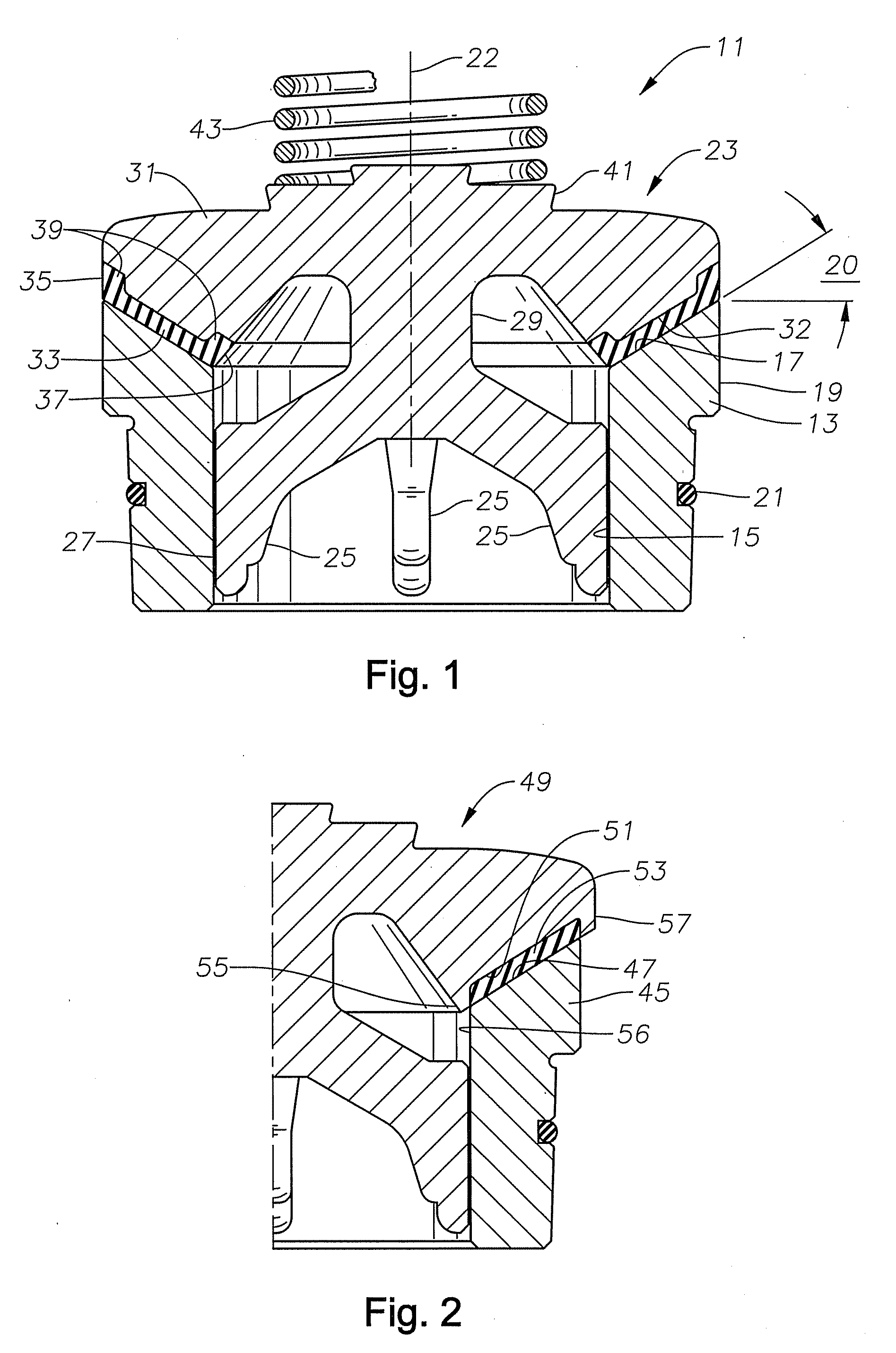
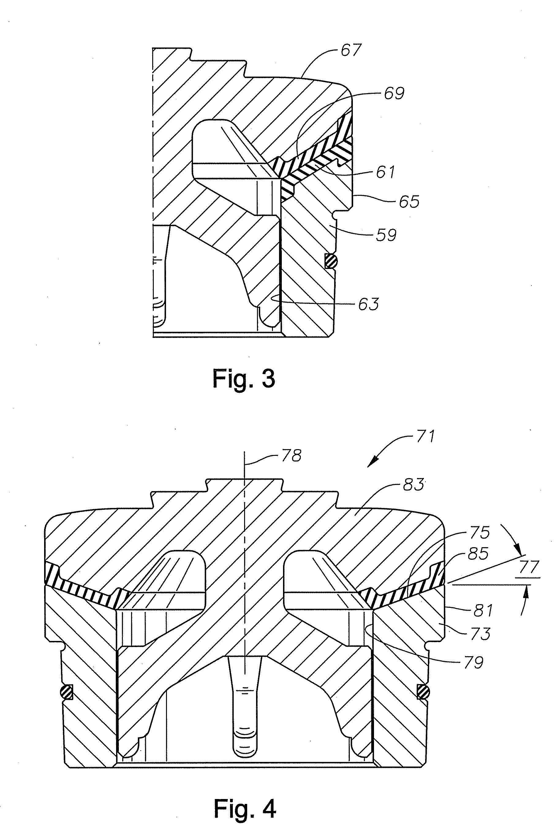
[0006]In one embodiment, a valve assembly is provided. The valve assembly includes a valve seat body having an axial bore therethrough. The valve seat body includes an inclined seat surface located on an upper end of the seat body. The assembly includes a valve member having a valve body such that the valve body is positioned within the axial bore of the valve seat body. The assembly further includes a seal disposed between the seat surface of the seat body and an annular seal surface of the valve member such that the seal prevents contact between the seat surface of the seat body and the valve member.

Problems solved by technology

Reciprocating pumps are typically exposed to highly abrasive fluids, and high pressures, which can result in wear on valve surfaces.
Metal fatigue is induced when cyclical high pressure is applied to a valve body sealed against, and being distorted by, a web seat.
This distortion, plus impact loads secondary to valve closure and bending moments caused by pressure on the valve seal, causes non-uniform stresses in the flange, particularly in the two opposing walls of the flange's peripheral seal retention groove.
Because of high pump pressures (up to about 15,000 psi) that the valves experience and the abrasive solid particles suspended in drilling mud and other fluids, valves and valve seats typically wear at a very rapid rate and must be replaced frequently.
The extremely high differential pressures in the valve cause the conical portion of the valve body to engage the valve seat with a very high impact.
The repetitive impact eventually causes the faces of the valve body and the valve seat to become worn and pitted.

Method used


Image

  • Pump Valve with Full Elastomeric Contact on Seat
  • Pump Valve with Full Elastomeric Contact on Seat
  • Pump Valve with Full Elastomeric Contact on Seat

Examples


Embodiment Construction

[0015]As used herein, a “valve assembly” suitable for abrasive fluids, such as oil field drilling mud, includes a valve body (the moving element) and a corresponding valve seat.

[0016]Referring to FIG. 1, valve assembly 11 is of a type of valve which is suitable to be installed with a reciprocating pump (not shown), particularly a large, high pressure pump for oilfield applications, such as hydraulic fracturing. In hydraulic fracturing operations, the pump pumps fracturing fluid into a wellbore at a high pressure. Valve assembly 11 includes a seat body 13 that mounts within a manifold of the pump. Seat body 13 is a tubular member typically formed of metal, such as cast steel. Seat body 13 has an axial bore 15. An inclined seat surface 17 is located on the upper end of seat body 13. Seat surface 17 is a conical surface extending from bore 15 to an outer diameter portion 19 of seat body 13. The conical contour of seat surface 17 is at a single angle 20, thus appears straight when viewe...


PUM


Abstract

This invention relates to valve assemblies having a valve seat body having an axial bore therethrough; wherein the valve seat body has an inclined seat surface located on an upper end of the seat body. The valve assemblies further include a valve member having a valve body such that the valve body is positioned within the axial bore of the valve seat body. A seal is disposed between the seat surface of the seat body and an annular seal surface of the valve member such that the seal prevents contact between the seat surface of the seat body and the valve member.

Description

Field of the Invention[0001]This invention relates in general to valves for reciprocating oilfield pumps, and in particular to a valve member having full elastomeric contact with a valve seat.BACKGROUND OF THE INVENTION[0002]Various kinds of pumps are used in oilfield operations. One type of pump, for example, is a reciprocating pump. The reciprocating pump can be used to pump fluid such as chemicals, cement, mud, or other media into a wellbore. Reciprocating pumps typically increase the pressure within a cylinder by reciprocating a plunger longitudinally within the cylinder. Packing is generally used around the plunger and the plunger reciprocates as a crankshaft located within the pump rotates. As the plunger moves away from the cylinder, the pressure of the fluid inside chamber decreases creating a differential pressure across an inlet valve that allows the fluid to enter the cylinder. As plunger moves longitudinally towards the cylinder, the pressure of the fluid inside of the c...

Claims


Application Information

Patent Timeline
IPC IPC(8): F16K25/00F16K17/04F16K1/32
CPCF16K25/005Y10T137/7925F04B53/102F16K15/063F16K1/46F16K1/465F04B53/10
Inventor HAWES, JOHN E.
Owner WEIR SPM
Learn More