Microfluidic system and method for assembling and for subsequently cultivating, and subsequent analysis of complex cell arrangements

a microfluidic system and cell technology, applied in the direction of diaphragms, electrostatic separators, electric/magnetic elements, etc., can solve the problems of large expenditures, low predictive power, and low efficiency

Active Publication Date: 2011-04-07
NMI NATURWISSENSCHAFTLICHES & MEDIZINISCHES INST AN DER UNIV TUBINGEN
View PDF10 Cites 28 Cited by
  • Summary
  • Abstract
  • Description
  • Claims
  • Application Information

AI Technical Summary

Benefits of technology

[0019]In view of the above, it is an object of the present invention to provide an apparatus and a method of the type mentioned at the outset wi

Problems solved by technology

The result thereof is an only limited informative power of the experiments carried out with the known cell cultures in relation to behaviour (toxicity, metabolism, mechanisms of action) in vivo, so that for example side effects of medicaments are often discovered only in clinical studies when the product is administered to patients, and large expenditures have already been made for research and development.
Another approach to the determination of the toxicity of medicaments are animal experiments, but use thereof is declining, besides their informative power being only provisionally applicable to humans, also for ethical reasons.
A further approach consists of investigating the effect of medicaments on isolated cells, but the predictive power is also limited here, as with the abovementioned 2D cell cultures, since single cells or two

Method used


Image

  • Microfluidic system and method for assembling and for subsequently cultivating, and subsequent analysis of complex cell arrangements
  • Microfluidic system and method for assembling and for subsequently cultivating, and subsequent analysis of complex cell arrangements
  • Microfluidic system and method for assembling and for subsequently cultivating, and subsequent analysis of complex cell arrangements

Examples


Embodiment Construction

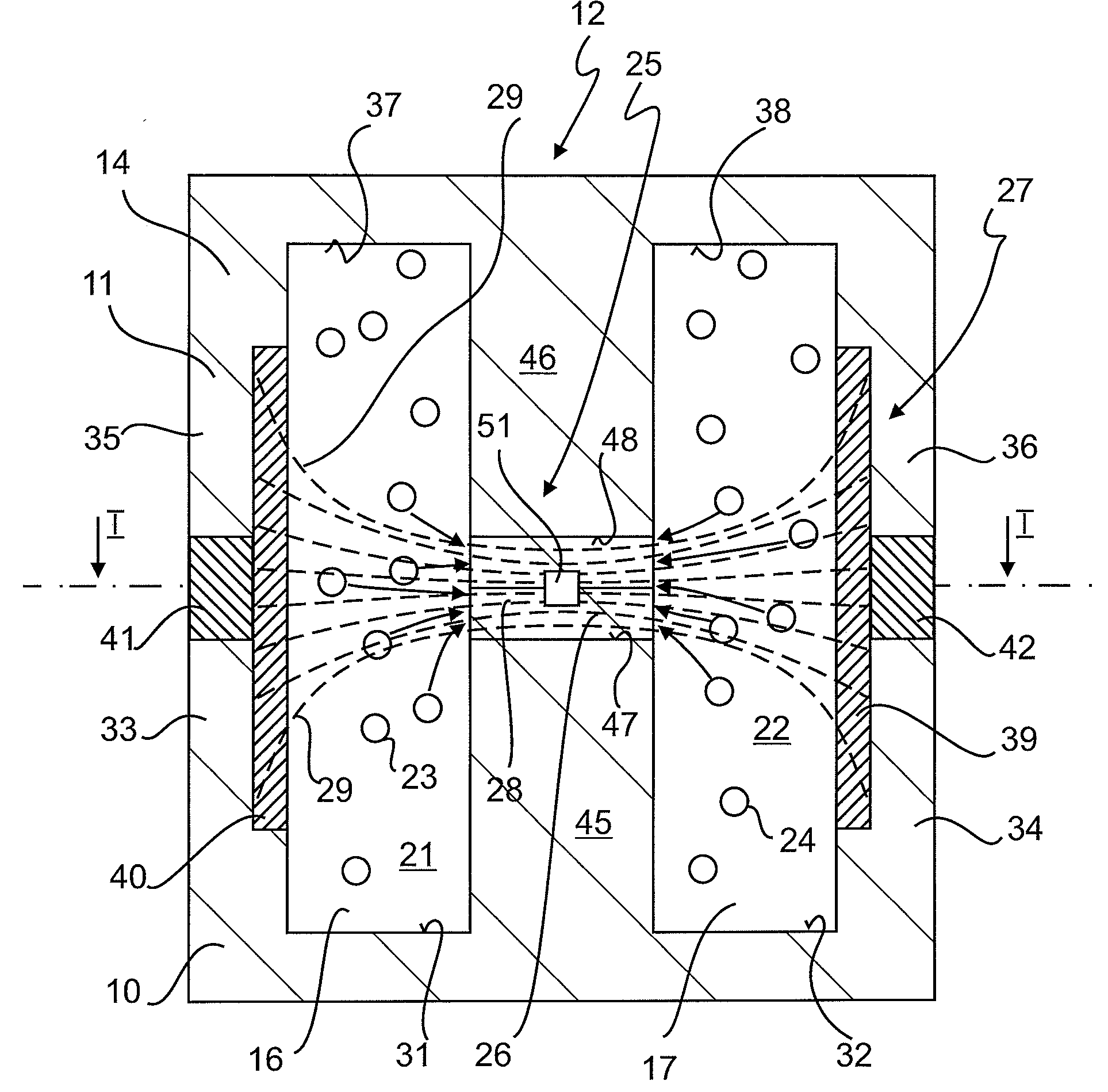
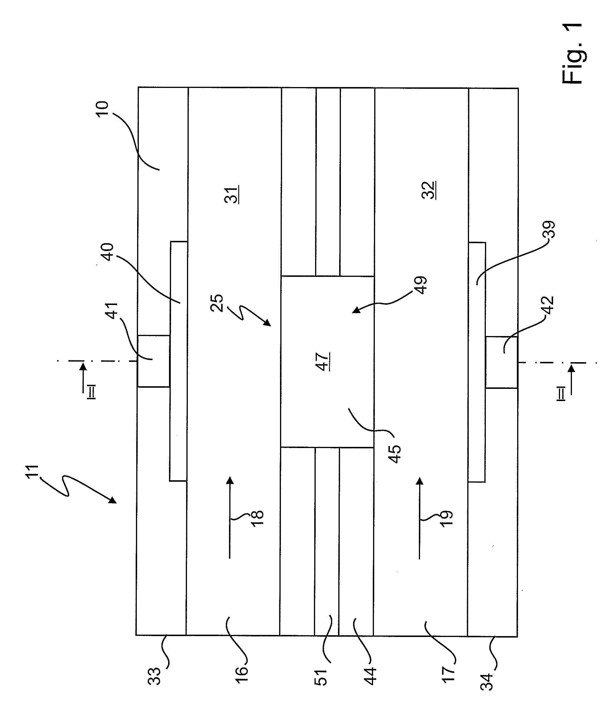
[0103]FIG. 1 depicts a diagrammatic plan view, in the form of a detail not true to scale, of a lower part 10 of a first embodiment of a microstructure 11 of a microfluidic system.

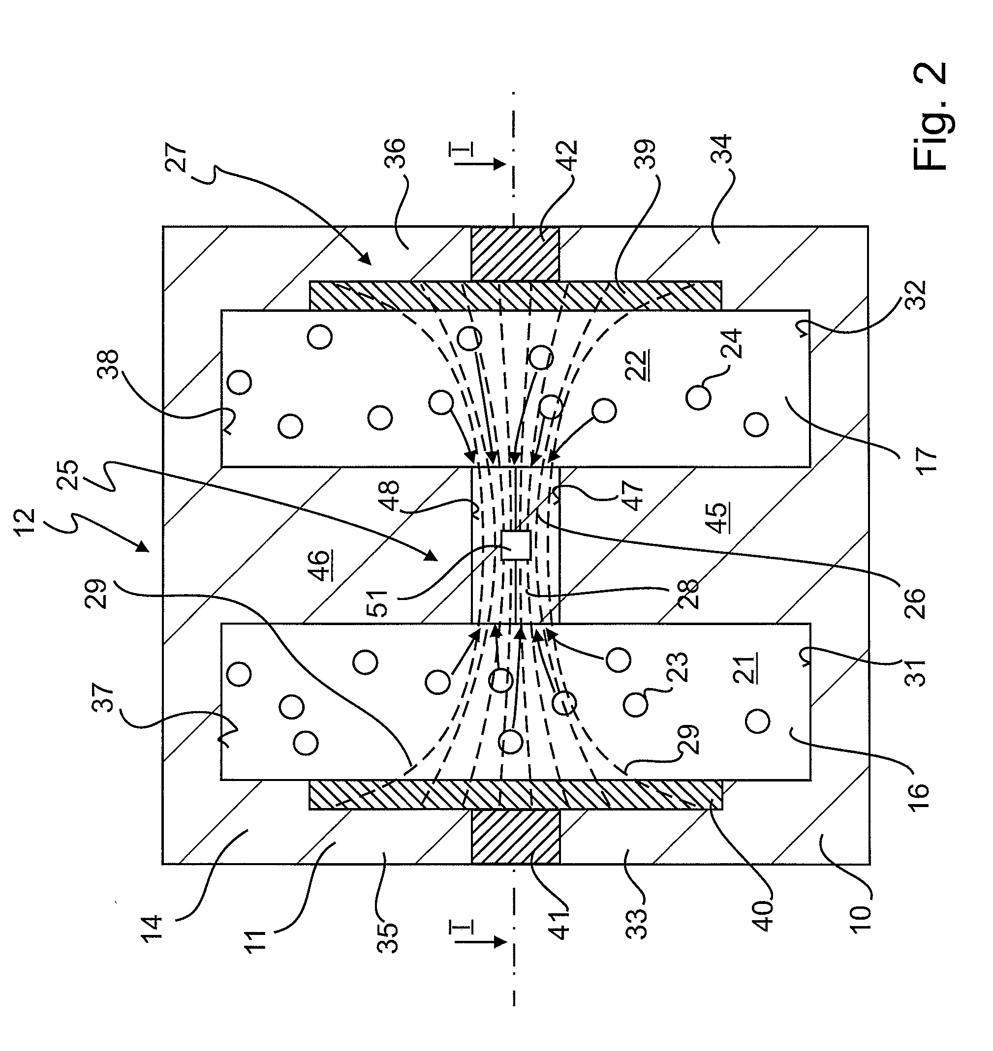
[0104]FIG. 2 shows a section transversely through the microfluidic system 12 along the line II-II in FIG. 1, while the plan view in FIG. 1 is viewed along the line I-I in FIG. 2.

[0105]The microstructure 11 has an upper part 14 which corresponds in geometric structure to the lower part 10 and which closes the lower part 10.

[0106]Two microchannel segments 16, 17 run through the microstructure 11 in parallel with and at a distance from one another, which are formed, in the example shown, partly in the lower part 10 and partly in the upper part 14. It is, of course, possible also for the microchannel segments 16 and 17 to be formed entirely in the lower part 10 or in the upper part 14, and then the upper 14 and the lower part 10 forming merely a channel cover and channel base, respectively.

[0107]The microstruct...


PUM

PropertyMeasurementUnit
Flow rateaaaaaaaaaa
Structureaaaaaaaaaa
Microstructureaaaaaaaaaa

Abstract

A microfluidic system (12) for assembling and subsequently investigating complex cell arrangements has a three-dimensional microstructure (11) in which the cell culture is assembled, cultivated and investigated. At least two microchannel segments (16, 17) through which the microstructure (11) can be perfused from outside with a medium (21, 22) run in the microstructure (11), whereby the microchannel segments (16, 17) run at least in sections approximately parallel or equidistant to one another. The two microchannel segments (16, 17) are separated from one another by a wall structure (25) in which at least one aperture (26) connecting the two microchannel segments (16, 17) is provided. An electrode arrangement (27) is provided in or on the microstructure (11) in order to generate an inhomogeneous electric field (28) in the region of the at least one aperture (26). A cell arrangement is assembled in this microstructure (11) by supplying medium (21, 22) with cells (23, 24) for assembling the cell culture in the microstructure (11), with the inhomogeneous electric field (28) determined by the microstructure (11) bringing about the assembling of the cell arrangement from the supplied cells (23, 24).

Description

[0001]This is a continuation application of copending international patent application PCT / EP2009 / 002332, filed Mar. 31, 2009, and designating the United States, which was published in English as WO 2009 / 121555 A2, and claims priority to German patent application DE 10 2008 018 170.6, filed Apr. 3, 2008. The contents of these prior applications are incorporated herein by this reference in their entireties.BACKGROUND OF THE INVENTION[0002]1. Field of the Invention[0003]The present invention relates to a microfluidic system for assembling and for subsequently analysing complex cell arrangements, and to a corresponding method.[0004]2. Related Prior Art[0005]In many areas of scientific research and of diagnosis, whether in a research laboratory or in the daily work of a laboratory concerned with routine investigations, there is a need for complex cell arrangements which can be perfused under conditions which are as physiological as possible, meaning for example being present in the anat...

Claims


Application Information

Patent Timeline
IPC IPC(8): G01N27/447
CPCB01L3/5027C12M21/08C12M33/00C12M35/02C12M23/16
Inventor STELZLE, MARTINANGRES, BRIGITTEKUBON, MASSIMOSCHUETTE, JULIAHAGMEYER, BRITTAHOLZNER, FELIX
Owner NMI NATURWISSENSCHAFTLICHES & MEDIZINISCHES INST AN DER UNIV TUBINGEN
Why Eureka
Try Eureka