Process for coating a part with an oxidation-protective coating

Active Publication Date: 2014-01-02
COMMISSARIAT A LENERGIE ATOMIQUE ET AUX ENERGIES ALTERNATIVES +1
View PDF2 Cites 15 Cited by
  • Summary
  • Abstract
  • Description
  • Claims
  • Application Information

AI Technical Summary

Benefits of technology

[0133]The method according to the invention, because it uses a single specific powder, sintered by a specific SPS method, gives the possibility for the first time of preparing a monolayer coating having a specific structure which is a three-dimensional microstructure.
[0134]This coating having this specific structure provides, while only consisting of one single layer, a protection against oxidation which is efficient at high temperature

Problems solved by technology

They retain their breaking stress and their modulus at temperatures of more than 2,000° C. However, within the scope of prolonged use in an oxidizing medium, they rapidly lose any mechanical property and this from 400° C. This is why, for overcoming this major problem, about twenty years ago, composites with an SiC matrix and with C fibers were first of all developed and then with SiC fibers when the latter were available on the market.
However, if SiC/SiC or C/SiC composites have better resistance to oxidation than C/C composites, they cannot be used at temperatures above 1,200° C.
The main problem which is posed upon using iridium in order to achieve PAO, is the extreme volatility of iridium oxides (IrO2 and IrO3).
Further, the coefficient of expansion difference between iridium and carbon makes it difficult to obtain an adherent PAO.
As a conclusion, the drawbacks of PAOs based on noble me

Method used


Image

  • Process for coating a part with an oxidation-protective coating
  • Process for coating a part with an oxidation-protective coating
  • Process for coating a part with an oxidation-protective coating

Examples


example 1

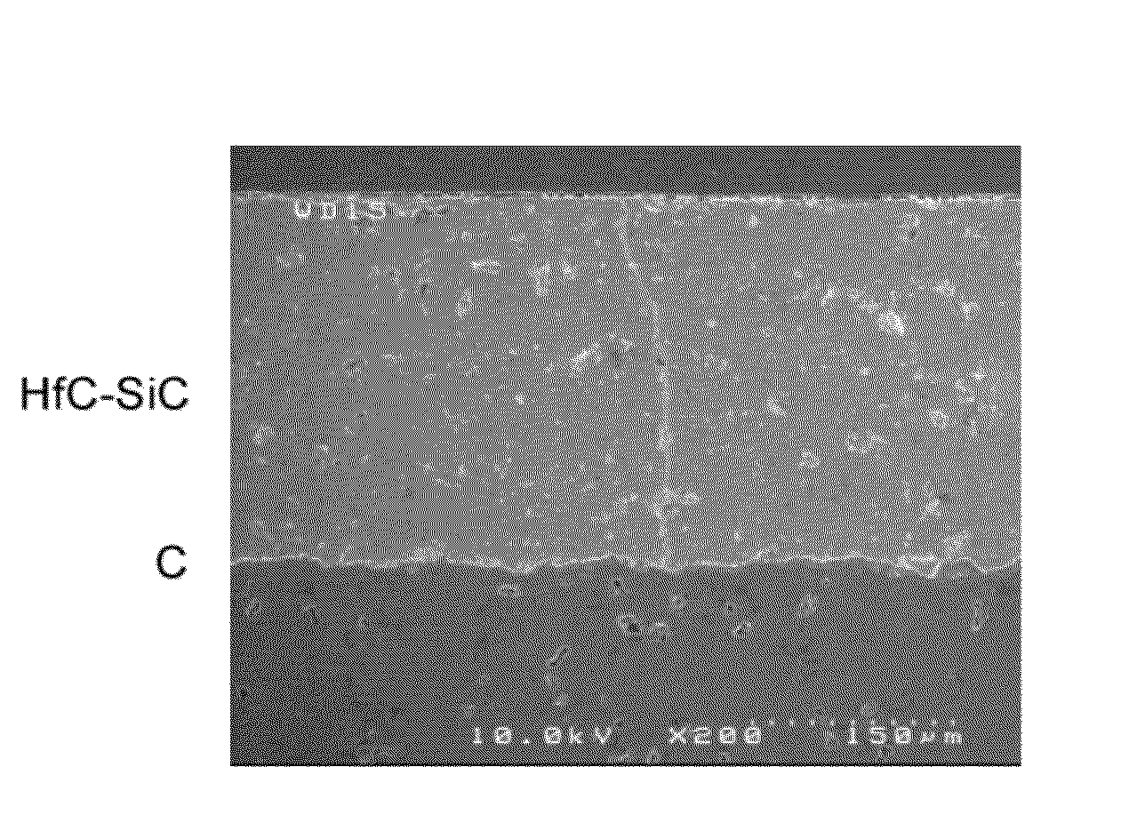
[0283]In this example, a protective coating against oxidation (PAO) is prepared by SPS sintering of a hafnium carbide (HfC) powder coated with silicon carbide (SiC), on a carbonaceous substrate.

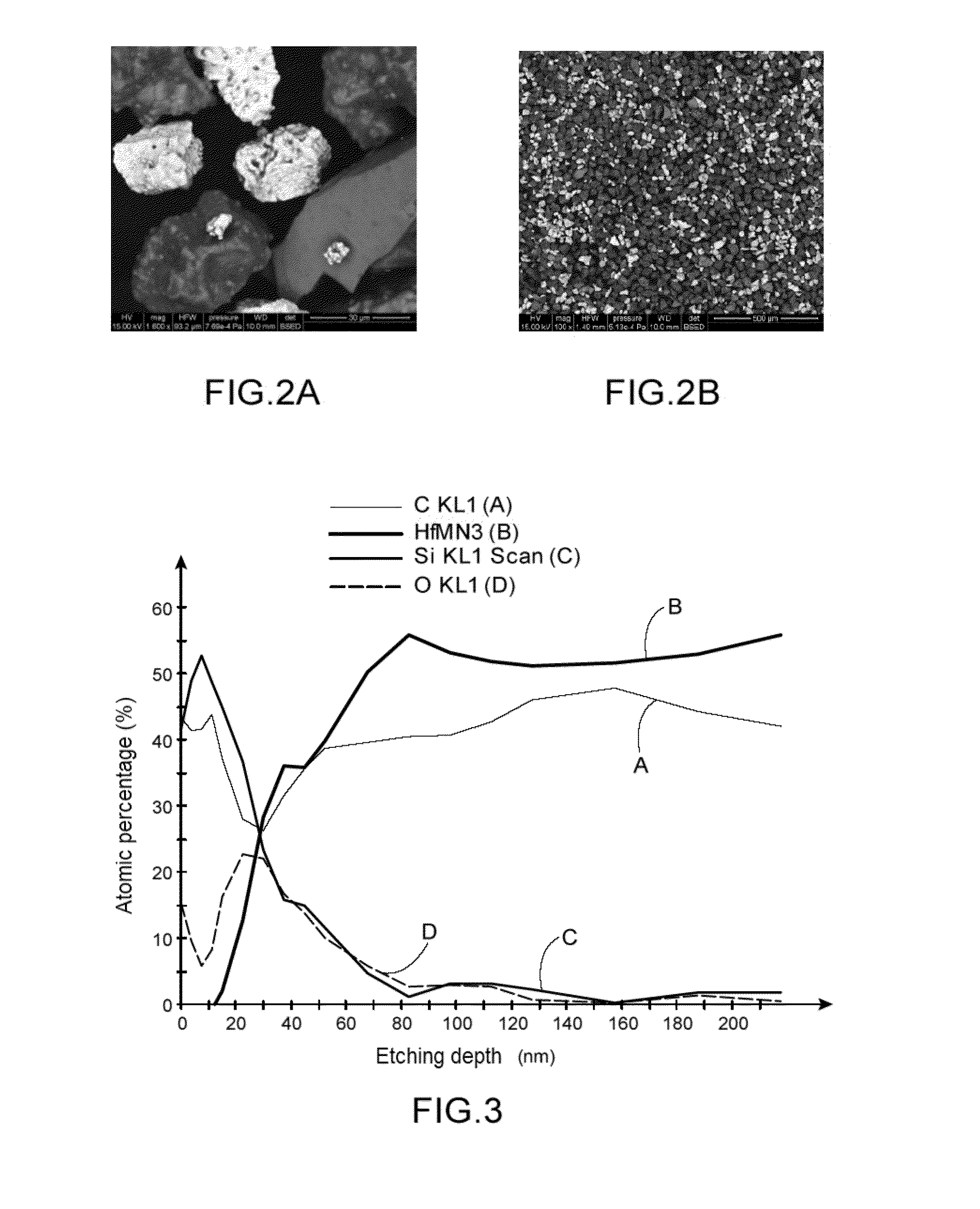
[0284]The HfC powder coated with SiC is prepared from an initial HfC powder which has a d50 of 35 μm.

[0285]The SiC coating of the powder is achieved by chemical vapor deposition (CVD) in a fluidized bed.

[0286]Hexamethyldisilane is used as a precursor of SiC for promoting deposition of SiC on the HfC powder.

[0287]The deposition operation is carried out under hydrogen (which plays a transport and reduction role) and under nitrogen (which plays the role of a fluidization gas) at about 900° C.

[0288]The deposition operation lasts for about 1 day taking into account the rise and the decrease of the temperature.

[0289]One of the benefits of the HfC powder coated with SiC stems from the fine adjustment between the coefficients of expansion of SiC, of HfC and of the substrate.

[0290]The benefit of SiC i...

example 2

[0314]In this example, a protective coating against oxidation (PAO) is prepared by SPS sintering of a hafnium carbide (HfC) powder coated with silicon carbide (SiC), coated with Ti, on a carbonaceous substrate.

[0315]The hafnium carbide (HfC) powder coated with silicon carbide (SiC), coated with Ti, is prepared by coating with titanium the hafnium carbide (HfC) powder coated with silicon carbide (SiC) prepared in Example 1.

[0316]The titanium carbide coating is made by chemical vapor deposition (CVD) in a fluidized bed.

[0317]The precursor used is titanium chloride, associated with a complexing agent.

[0318]The Ti layer with which the particles of the powder prepared in this example are provided, have a double benefit, i.e.:[0319]the titanium layer gives the possibility of facilitating sintering;[0320]during sintering, the titanium may carburize upon contact with the carbonaceous substrate so as to form TiC, a refractory carbide, and promote adhesion of the coating to the substrate.

[032...

example 3

[0353]In this example, thermogravimetric analyses (TGA) were conducted on the crude HfC powder (powder without any coating as described in Example 1) as well as on the HfC powder coated with SiC (prepared in Example 1) and on an SiC powder with a grain size d50=35 μm identical with the previous ones.

[0354]The analyzer is a thermobalance more exactly a mono-furnace SETARAM TG 92® apparatus equipped with a thermocouple of type S.

[0355]With sweeping of dry compressed air, the samples are positioned in a rod for Differential Scanning Calorimetry or DSC.

[0356]The maximum temperature reached is 1,500° C. and the rise kinetics are set to 10° C. / min.

[0357]FIG. 8 shows the time-dependent change of the mass gain versus temperature.

[0358]The mass gain is directly linked to oxidation, the greater the mass gain, the more the material is oxidized.

[0359]FIG. 8 shows a mass gain of more than 10% for crude HfC (Curve B) with oxidation which starts from 400° C. and which is disastrous between 500 and...


PUM

PropertyMeasurementUnit
Grain sizeaaaaaaaaaa
Temperatureaaaaaaaaaa

Abstract

A method for preparing a protective coating against oxidation on at least one surface of at least one part made of at least one material capable of being oxidized, wherein the following successive steps are carried out:
    • a) each of the particles of a powder made of a first ceramic selected from refractory ceramics and ceramics which resist oxidation, is coated with at least one layer selected from layers made of a refractory ceramic, layers made of a ceramic which resist oxidation, and layers made of a refractory metal, provided that the coating comprises at least one ceramic which resists oxidation, and at least one refractory ceramic or metal;
    • b) the powder is deposited onto the surface to be coated of the part;
    • c) sintering of the powder is achieved on the surface of the part by a Spark Plasma Sintering (SPS) Method;
    • d) the part is cooled;
    • e) the cooled part, coated on at least one of its surfaces with a protective refractory monolayer coating against oxidation, with a three-dimensional microstructure, is recovered.

Description

TECHNICAL FIELD[0001]The invention relates to a method for coating a part with a protective coating against oxidation (oxidation-protective coating).[0002]More specifically, the invention relates to a method for coating at least one surface of at least one part made of at least one material capable of being oxidized, with a protective coating against oxidation.[0003]The technical field of the invention may be generally defined as that of oxidation protection or PAO (Protection Against Oxidation).[0004]The technical field of the invention is in particular that of protection against high temperature oxidation, generally at a temperature above 1,200° C. of materials sensitive to oxidation, such as composite materials and notably carbon / carbon composite materials.BACKGROUND ART[0005]Composite materials such as carbon / carbon composite materials (CIC) have been known for more than thirty years for their excellent resistance to temperature and their resistance to thermal shocks. They retai...

Claims


Application Information

Patent Timeline
IPC IPC(8): B05D5/00
CPCB05D5/00C04B35/5622C04B35/62834C04B35/62842C04B35/62884C04B35/62894C04B35/62897C04B35/645C04B41/0072C04B41/009C04B41/4584C04B41/52C04B41/87C04B2235/3839C04B2235/3843C04B2235/5436C04B2235/6562C04B2235/6565C04B2235/6567C04B2235/666C04B2235/77C04B2235/80C23C24/08C23C26/00C23C28/04C04B41/0054C04B41/4521C04B41/5057C04B41/5059C04B41/4531C04B41/457C04B41/5133C04B35/522C04B35/83
Inventor ALLEMAND, ALEXANDRESZWEDEK, OLIVIERBIANCHI, LUCLE PETITCORPS, YANN
Owner COMMISSARIAT A LENERGIE ATOMIQUE ET AUX ENERGIES ALTERNATIVES
Why Eureka
Try Eureka