Connecting structure

a technology of connecting structure and lid body, which is applied in the direction of liquid handling, applications, caps, etc., can solve the problems of manual disabled persons, children, elderly and manual disabled persons, and affecting the operation of the lid body,

Inactive Publication Date: 2011-04-07
NAKAMURA KOHEI
View PDF17 Cites 7 Cited by
  • Summary
  • Abstract
  • Description
  • Claims
  • Application Information

AI Technical Summary

Benefits of technology

[0018]The present invention can provide a connecting structure which can be connected by slight rotation of a second member with res

Problems solved by technology

Thus, if a user is careless about a rotating direction of a lid body to open/close the same, the lid body would be rotated in an opposite direction, resulting in wrong and bothersome operation.
In particular, left-handers have difficulty opening/closing the lid body on most occasions.
In addition, a screw-type connecting structure requires at least 2 or 3 rotations to completely fasten a lid body, which can cause children, the elderly and manually disabled persons an onerous operational problem.
In operation, as a lid is rotated, the projection and the groove can generate a significant friction, leading to a difficulty in smoothly opening/closing the lid.
Also, a groove described in Patent Documents 2 and 3 allows sand or dust to enter inside thereof, thereby making it difficult to remove such a foreign substance.
Specifically, sand

Method used


Image

  • Connecting structure
  • Connecting structure
  • Connecting structure

Examples


example 1

[0147]Next, a specific Example 1 of a connecting structure according to the present invention will be described. In this Example 1, a connecting structure according to the present invention is applied as a structure for connecting a prescribed gas injecting tool to a gaseous structure 2D as a first member 2 having a flat valve device 4 (U.S. Pat. No. 3,504,945) invented by this inventor via an adapter 3D as a second member 3.

[0148]First, a constitution of a flat valve device 4 of this Example 1 will be described. The flat valve device 4, as shown in FIGS. 17 to 19, mainly comprises an external frame member 41 composed of a connecting upright portion 21 of the gaseous structure 2D, a body member 42 which is detachably mounted on the opening 20 of the external frame member 41, a rotary lid 43 which is rotatably mounted on the body member 42 and a valve mechanism 44 provided inside the body member 42.

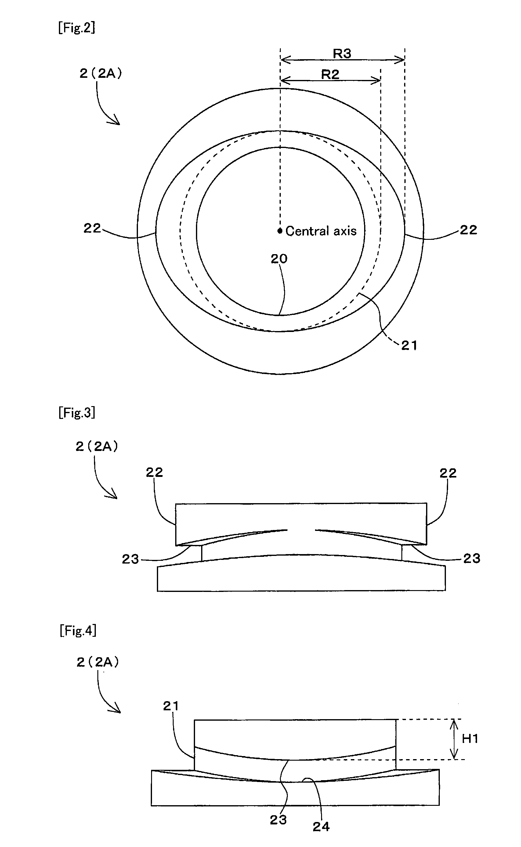
[0149]In this Example 1, two locking flanges 22 are projected at symmetrical positions...

example 2

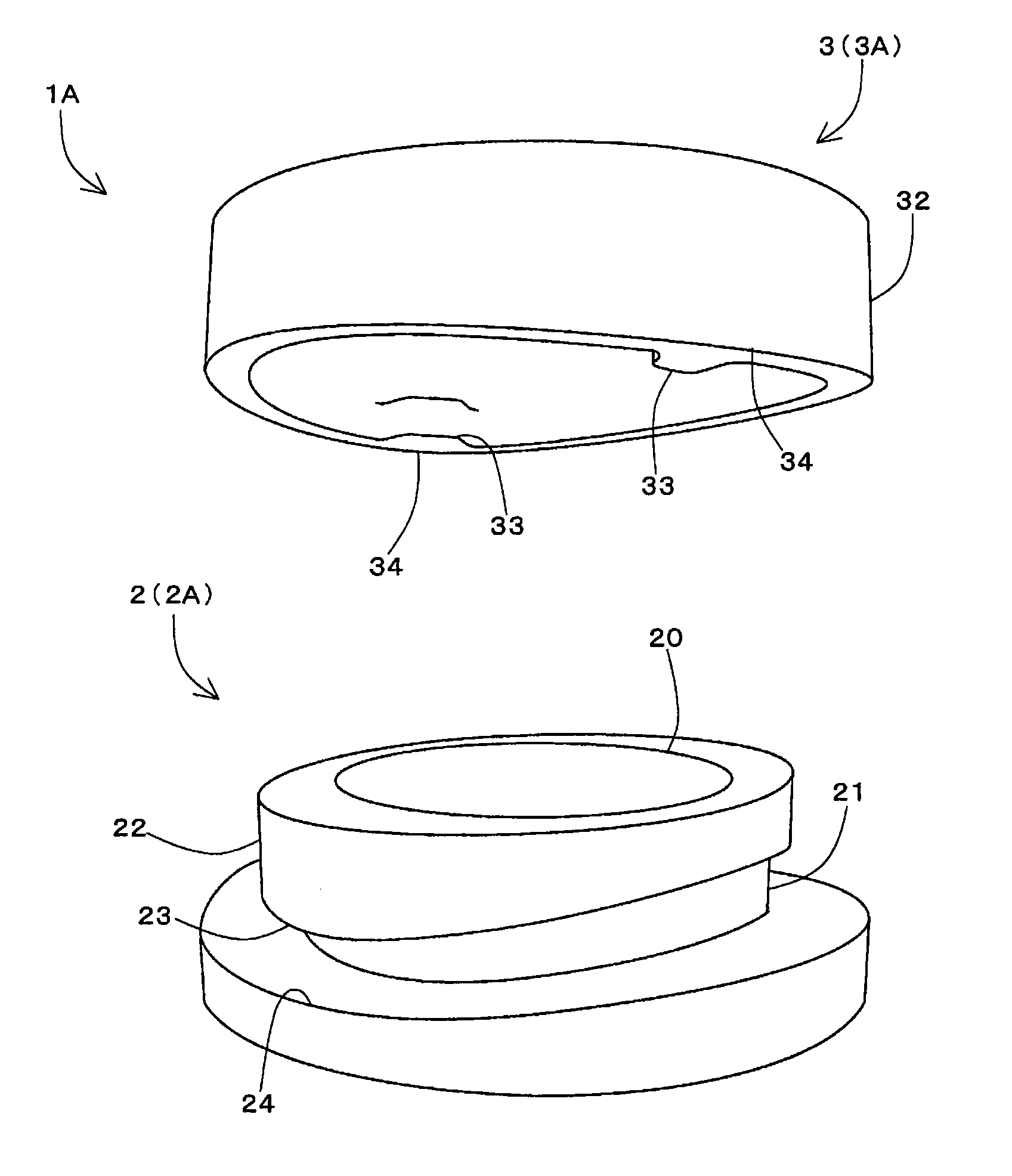
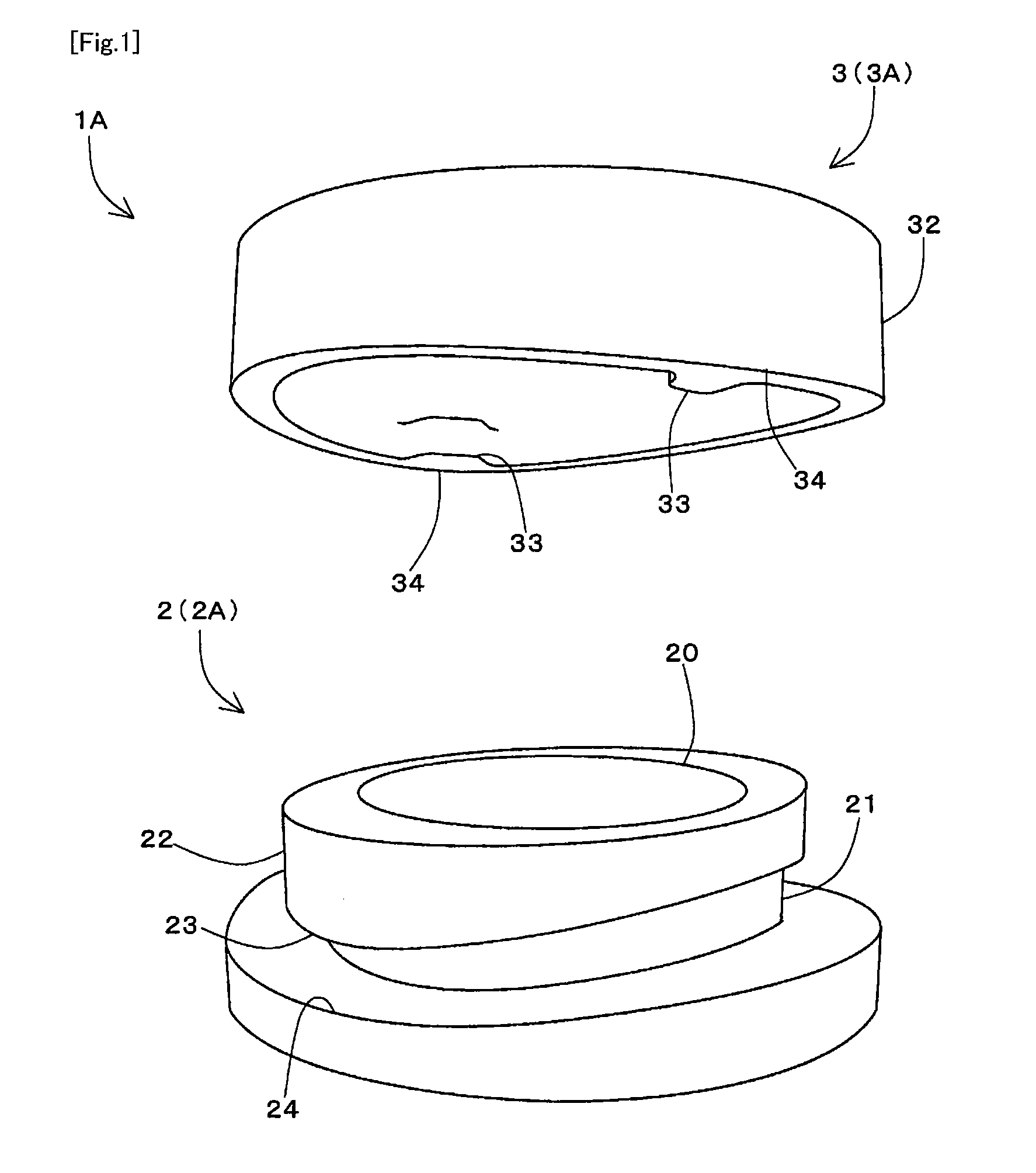
[0160]Next, a specific Example 2 of a connecting structure according to the present invention will be described. In this Example 2, a plastic bottle 2E is employed as a first member 2, and a connecting structure according to the present invention is applied as a structure for connecting a cap 3E as a second member 3 to an opening 20 of the plastic bottle 2E.

[0161]Specifically, as shown in FIG. 25, a drinking portion of the plastic bottle 2E of this Example 2 is provided substantially similarly to the container body 2A corresponding to the aforementioned first embodiment. Meanwhile, the cap 3E is provided substantially similarly to the lid body 3A corresponding to the aforementioned first embodiment and provided with a sealing member 35 for improving watertightness.

[0162]The aforementioned this Example 2 can readily and swiftly attach the cap 3E to or detach the same from a plastic bottle 2E without reducing watertightness.

example 3

[0163]Next, a specific Example 3 of a connecting structure according to the present invention will be described. In this Example 3, a connecting structure according to the present invention is applied as a structure for connecting plastic bottles.

[0164]Specifically, as shown in FIG. 26, a plastic bottle P of this Example 3 is provided with each of constituted portions of a first member 2 formed at a lower position of a normal cap C, and each of constituted portions of a second member 3 is formed on a bottom face of the plastic bottle P. In this Example 3, each of the constituted portions as a first member 2 is provided substantially similarly to the aforementioned first embodiment. Meanwhile, each of the constituted portions as a second member 3 is formed so that a dimension from a ceiling plane of the lid portion 31 to an upper end surface of the locking projections 33 (H2) is enough to accommodate the cap C.

[0165]The aforementioned this Example 3, as shown in FIG. 26, can save spa...


PUM


Abstract

Disclosed is a connecting structure for connecting a first member and a second member, wherein the first member comprises a connecting upright portion and a plurality of locking flanges provided to extend outwards along the circumferential direction of the outer face of the connecting upright portion, while the second member comprises a connecting side-wall portion that overlies the connecting upright portion and a plurality of locking projections provided to extend inwards from the inner face of the connecting side-wall portion. The bottom faces of the locking flanges distend downwards in a convex curved shape and, when the second member is overlaid on the first member and rotated, the upper faces of the locking projections are guided with sliding contact along the convex curved bottom faces of the locking flanges and stopped at the lowermost position of the convex curved bottom faces.

Description

CROSS REFERENCE TO RELATED APPLICATIONS[0001]This application is a U.S. national application of PCT International Application PCT / JP2009 / 059896, filed May 29, 2009, which claims priority to Japanese Application No. 2008-143011, filed May 30, 2008, the contents of each of which are incorporated by reference in their entirety for all purposes.FIELD OF THE INVENTION[0002]The present invention relates to a connecting structure for connecting a first member and a second member, and particularly to a connecting structure which is suitable for use in connecting a lid body to an opening of a container body such as a plastic bottle and water play equipment which can contain gas or liquid, and connecting various members as a pair of members to be locked therebetween such as a clasp of a bag and a button.BACKGROUND OF THE INVENTION[0003]A connecting structure for connecting a lid body to an opening of a container, etc. is proposed in conventional techniques. For example, Japanese Unexamined Pa...

Claims


Application Information

Patent Timeline
IPC IPC(8): B65D41/06
CPCB65D43/0231F16B21/04F16B21/165A44B1/32B65D41/04B65D41/0485F16B21/02F16K15/20A44B1/14A44B1/08A44B5/02B65D41/0492B65D21/0231B65D41/06B65D50/061B65D41/0471B65D2251/04
Inventor NAKAMURA, KOHEI
Owner NAKAMURA KOHEI
Why Eureka
Try Eureka