Electrically conductive yarn with reduced torsions

a technology of torsions and conductive yarns, applied in the field of electrically conductive yarns, can solve the problems of failure of yarns and yarns may no longer provide the function of heating elements in e, and achieve the effects of increasing reducing the life expectancy of applications comprising yarns, and affecting the flexlife of yarns

Inactive Publication Date: 2011-04-07
NV BEKAERT SA
View PDF22 Cites 6 Cited by
  • Summary
  • Abstract
  • Description
  • Claims
  • Application Information

AI Technical Summary

Benefits of technology

[0014]In general, a much higher number of torsions per meter is applied in yarn in order to obtain the various elements of the yarn (i.e. the fibres in a bundle or bundles) closely together. However, as surprisingly has been observed in the present invention, this high number of torsions may adversely affect the flexlife of the yarn. As a consequence, the life expectancy of the application comprising the yarn may be reduced. By selecting the number of torsions per meter according to the present invention, an increase of the flexlife of the yarns, and consequently an increased life time of the system wherein the yarns are applied, can be realised. Examples of applications wherein the flexlife of the yarns plays an important role are e.g. the use in heating applications such as a car seat heating. In order to keep the different elements of the yarn from spreading too far apart, it has been observed that a minimum number of approx. 10 torsions per meter is sufficient.
[0016]The equivalent diameter of the individual metal fibres is typically smaller than 50 μm, e.g. smaller than 40 μm, e.g. smaller than 20 μm. The fibre diameter is typically greater than 1 μm, e.g. greater than 2 μm, e.g. greater than 6 μm. It has been observed that a reduced fibre diameter also has a positive effect on the flexlife.

Problems solved by technology

When repeatedly subjected to such stresses, metal fibres of the yarn may break, eventually resulting in the failure of the yarn.
As a result, the yarn may no longer provide its function as a heating element in e.g. a car seat heating.

Method used


Image

  • Electrically conductive yarn with reduced torsions
  • Electrically conductive yarn with reduced torsions
  • Electrically conductive yarn with reduced torsions

Examples


Embodiment Construction

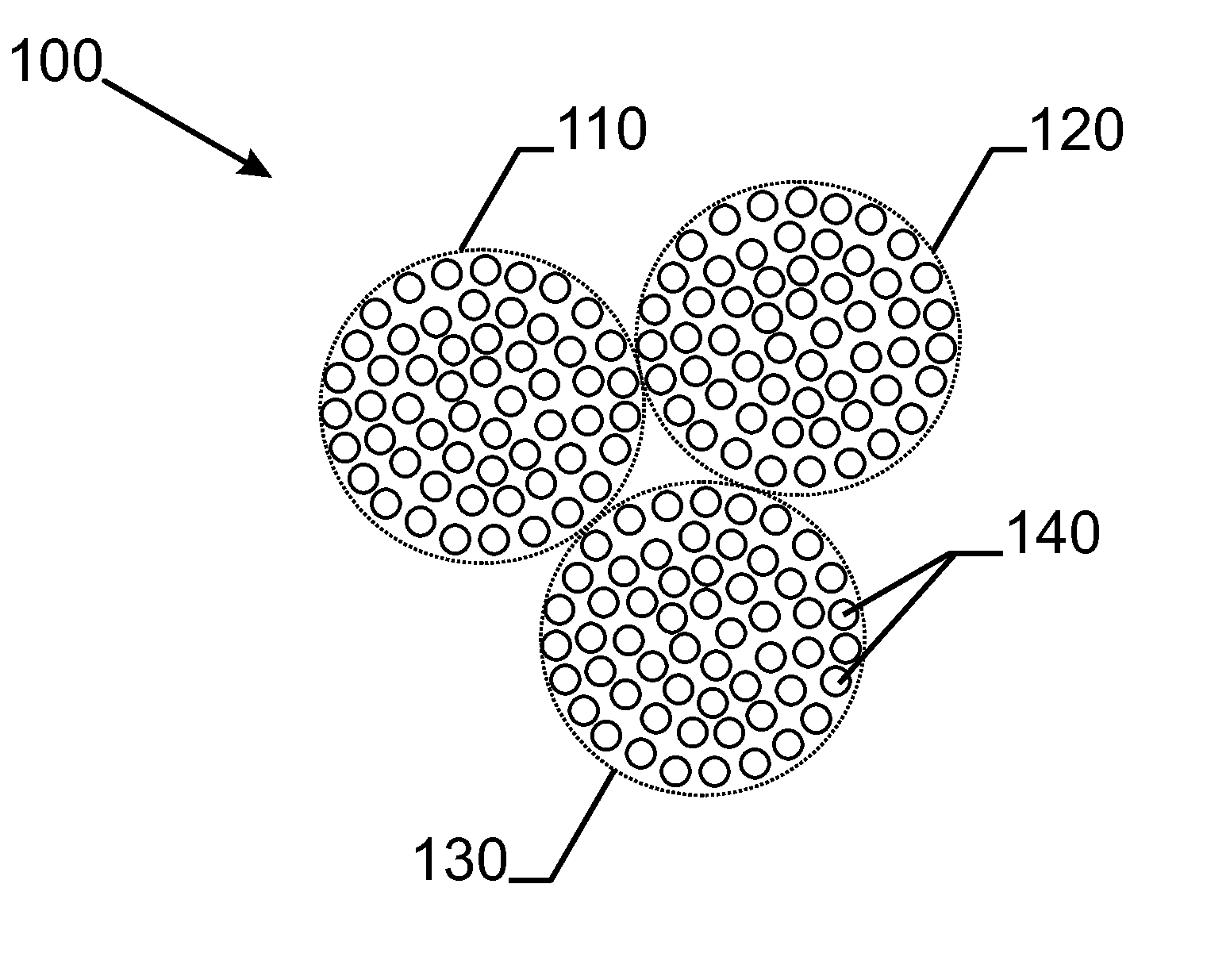
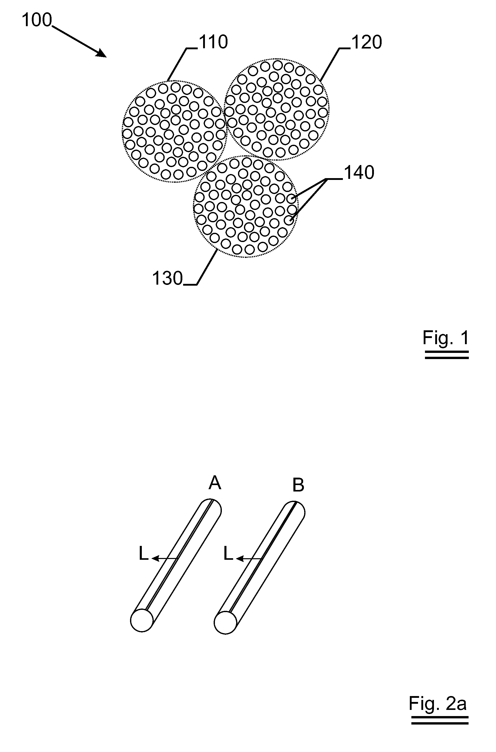
[0023]Yarns according to the present invention comprise one or more bundles of metal fibres, each bundle comprising at least 30 metal fibres. FIG. 1 schematically depicts a cross-sectional view of a yarn 100 according to the present invention. The yarn 100 comprises three bundles 110, 120 and 130 each comprising more than 30 metal fibres 140.

[0024]In the present invention, metal is to be understood as encompassing both metals and metal alloys (such as stainless steel) or compositions. As an example, the metal fibres as applied in the present invention may comprise a stainless steel core enclosed by copper or a copper alloy. Alternatively, the metal fibres as applied in a yarn according to the present invention may have a copper core surrounded by a stainless steel mantle. Such fibres provide improved electrical properties combined with the corrosion and oxidation resistance of stainless steel. Said stainless steel is preferable chosen out of AISI 300 series such as AISI 302, 304, 31...


PUM

PropertyMeasurementUnit
equivalent diameteraaaaaaaaaa

Abstract

A yarn (100) comprising one or more bundles (110, 120, 130), each of said one or more bundles comprising at least thirty metal fibres is described. The metal fibres (140) comprise stainless steel and a metal which is electrically more conductive than stainless steel. The yarn is twisted with a predetermined number of torsions per meter, said predetermined number of torsions per meter is smaller than 80 per meter and larger than 10 per meter. By doing so, an improved flexlife of the yarn can be obtained.

Description

TECHNICAL FIELD [0001]The present invention relates to an electrically conductive yarn comprising one or more bundles of metal fibres and to its various uses.BACKGROUND ART [0002]Yarns comprising one or more bundles of metal fibres are known. Such yarns are e.g. applied in vehicle seat heating systems or heatable textiles. In these applications, the yarns are used as an electrical resistance and provided, in use, with an electric current to obtain the required heating effect. In many of the applications of such yarns, the yarns are subjected to different stress and / or strain conditions. In particular, the yarns may be repeatedly loaded under tensile and / or bending or torsion stresses, e.g. when applied in a car seat heating. When repeatedly subjected to such stresses, metal fibres of the yarn may break, eventually resulting in the failure of the yarn. As a result, the yarn may no longer provide its function as a heating element in e.g. a car seat heating.DISCLOSURE OF INVENTION [000...

Claims


Application Information

Patent Timeline
Patent Type & Authority Applications(United States)
IPC IPC(8): D02G3/12D02G3/44H05B3/10H05B3/34B60N2/56
CPCB60N2/5685D02G3/12D02G3/446D02G3/441D02G3/28
Inventor DE GREVE, KRISAMILS, XAVIERVERSTRAETEN, STEVESPELEERS, POL
Owner NV BEKAERT SA
Why Eureka
Try Eureka