
Image forming apparatus and sheet conveying method that correct for skew of sheet conveyed to image forming unit

Inactive Publication Date: 2011-04-07
CANON KK
View PDF3 Cites 14 Cited by
  • Summary
  • Abstract
  • Description
  • Claims
  • Application Information

AI Technical Summary

Benefits of technology

[0011]The present invention provides an image forming apparatus and a sheet conveying method that can reliably correct for skew of a sheet being conveyed.
[0016]According to the present invention, because skew of a sheet is corrected for based on the skew amount of the sheet and the amount of toner used for an image formed on the sheet, skew of a sheet during conveyance of the sheet having an image formed on a first surface thereof so as to form an image on a second surface of the sheet can be reliably corrected for.

Problems solved by technology

Incidentally, to improve the performance of the image forming apparatuses, an image forming operation must be speeded up, but the above described loop forming system is not suitable because a sheet being conveyed must be temporarily stopped so as to form a loop in the sheet, and hence correction requires long time.
However, as the sheet conveying speed increases, rollers contacting on a sheet become more prone to slip.
In this case, an image formed on the sheet is misaligned to a large degree, and hence even in the above described active registration system, it is difficult to correct for the misalignment.

Method used


Image

  • Image forming apparatus and sheet conveying method that correct for skew of sheet conveyed to image forming unit
  • Image forming apparatus and sheet conveying method that correct for skew of sheet conveyed to image forming unit
  • Image forming apparatus and sheet conveying method that correct for skew of sheet conveyed to image forming unit

Examples


first embodiment

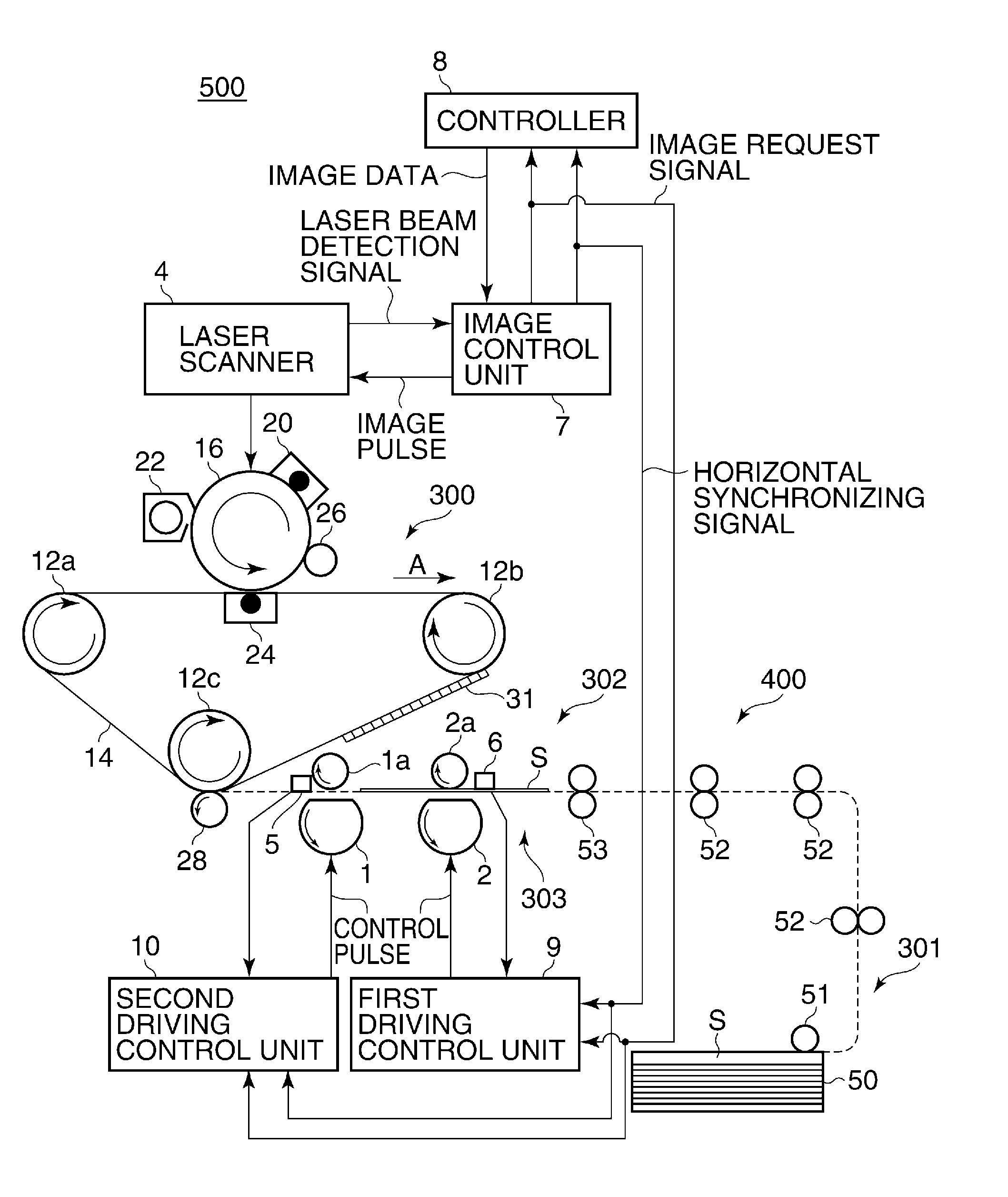
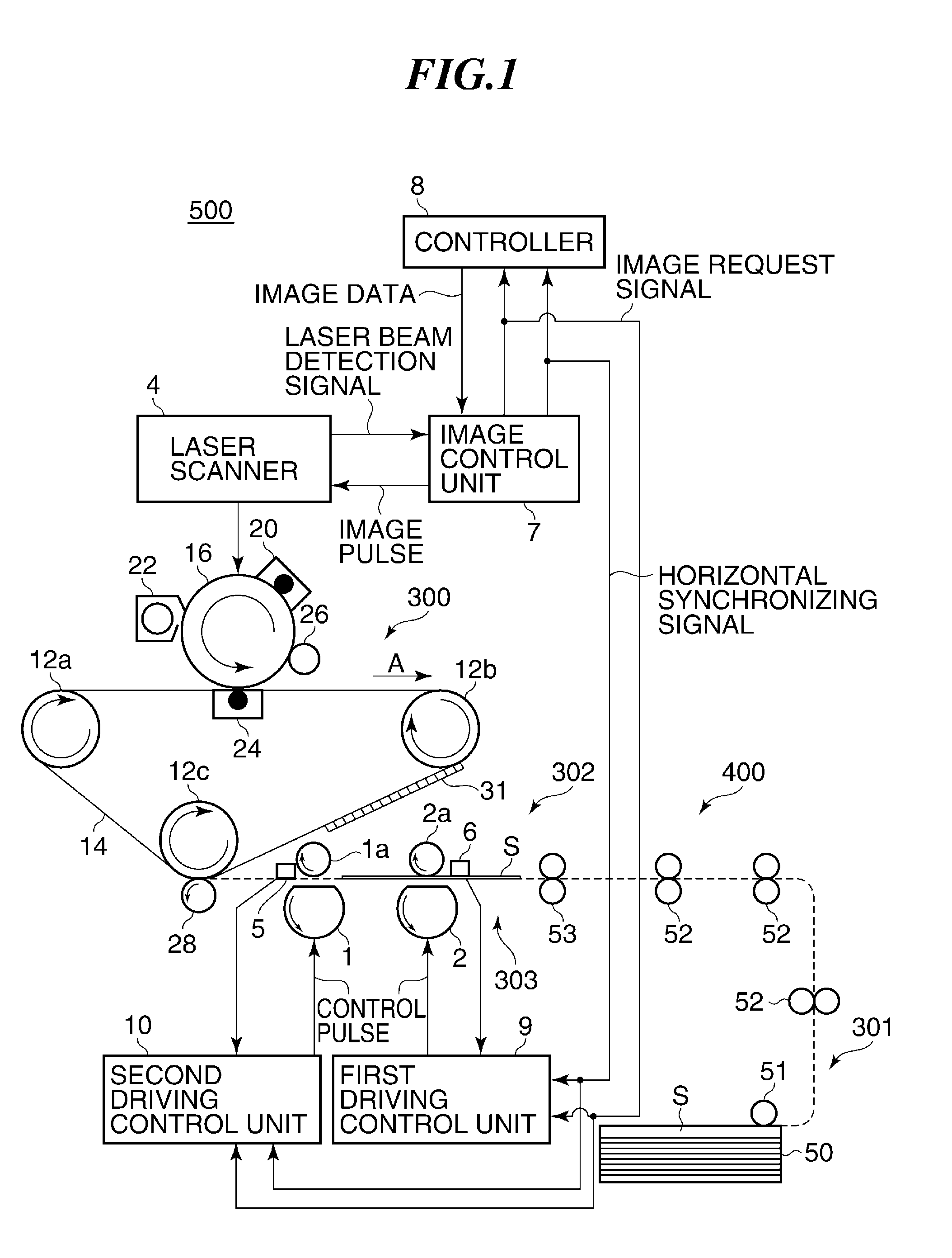
[0038]FIG. 1 is a diagram schematically showing an internal arrangement of an image forming apparatus according to the present invention.

[0039]Referring to FIG. 1, the image forming apparatus 500 has an image control unit 7 that controls the overall operation of the apparatus, a controller 8, an image forming unit 300 that forms an image on a sheet S, and a conveying unit 400 that conveys the sheet S.

[0040]The image control unit 7 generates a horizontal synchronizing signal based on a laser beam detection signal sent from a laser scanner 4, described later, and in synchronization with the horizontal synchronizing signal, sends an image pulse to the laser scanner 4. Also, the image control unit 7 sends an image request signal and a horizontal synchronizing signal to the controller 8, and converts image data sent from the controller 8 into an image pulse having a pulse width corresponding to a data level of the image data. The image request signal is generated by, for example, the ima...

second embodiment

[0121]Next, a description will be given of the present invention.

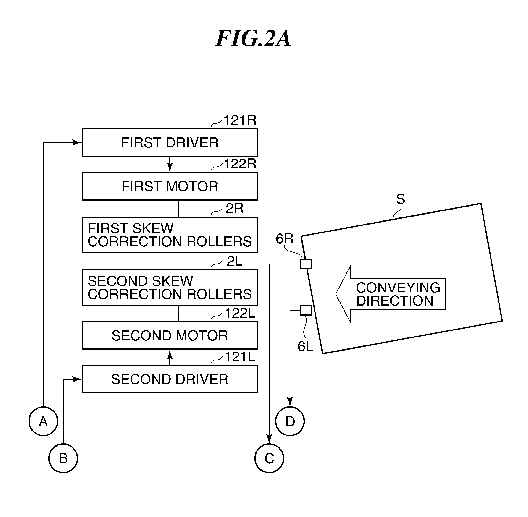
[0122]An image forming apparatus according to the second embodiment controls the skew correction roller pairs 2R and 2L based on the amount of toner used of an image formed on one surface of the sheet S and sheet surface characteristics.

[0123]The overall arrangement of the image forming apparatus according to the present embodiment is the same as that of the image forming apparatus 500 according to the first embodiment, and description of corresponding operations is omitted, only different operations being described below.

[0124]This image forming apparatus has an operation / display unit as shown in FIG. 16, and when a user inputs sheet surface characteristics such as a sheet surface friction coefficient μ, a sheet size, a mass per unit area, and the presence or absence of a coating from the operation / display unit, data on the sheet surface characteristics is stored in the image control unit 7. In this case, the image co...


PUM


Abstract

An image forming apparatus that can reliably correct for skew of a sheet being conveyed. The amount of skew of the sheet is detected, and the amount of toner used for an image formed on a first surface of the sheet is determined. When the sheet with the image formed on the first surface thereof is conveyed so as to form an image on a second surface of the sheet, a skew correction roller unit is controlled so as to correct for the skew of the sheet based on the detected amount of skew and the determined amount of toner used.

Description

BACKGROUND OF THE INVENTION[0001]1. Field of the Invention[0002]The present invention relates to an image forming apparatus and a sheet conveying method, and in particular to an image forming apparatus and a sheet conveying method that correct for skew of a sheet being conveyed to an image forming unit.[0003]2. Description of the Related Art[0004]Image forming apparatuses such as copiers, printers, and facsimiles have a conveying unit that conveys a sheet such as a recording sheet or an OHP sheet to an image forming unit. According to those image forming apparatuses, a sheet is conveyed to the image forming unit by the conveying unit, and an image formed by the image forming unit is transferred to the sheet, so that an image is formed on the sheet.[0005]Some of such image forming apparatuses having a conveying unit have a skew correction unit to correct for sheet skew so as to prevent a skewed sheet from being conveyed to the image forming unit, and correction systems using the skew...

Claims


Application Information

Patent Timeline
IPC IPC(8): G03G15/00B65H9/00B65H7/02
CPCB65H7/08G03G15/6567B65H2404/1411B65H2511/242B65H2511/514B65H2513/104B65H2513/11B65H2557/51B65H2701/1311B65H2701/1313B65H2801/06G03G2215/00561G03G2215/00565B65H9/002G03G15/6564B65H2220/03B65H2220/02B65H2220/01B65H2220/11B65H2511/24B65H2513/10
Inventor SAITO, HIROSHI
Owner CANON KK
Learn More