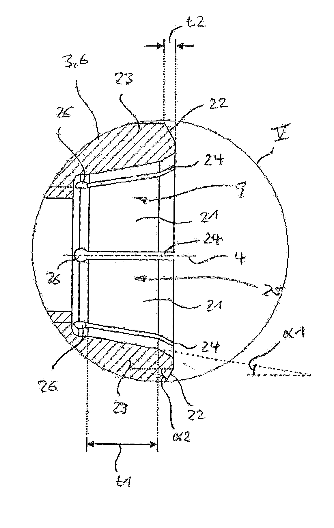
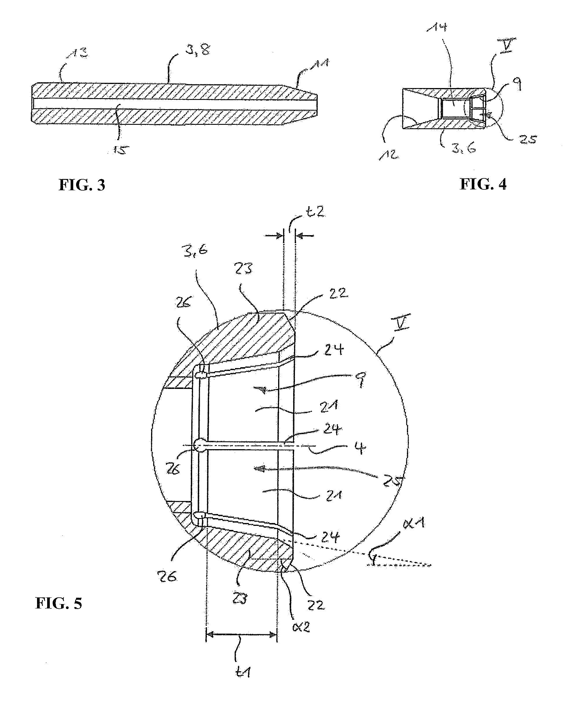
[0011]In the case of both variants of the tool interface according to the invention, the centering of the tool head in respect of the tool shank is effected primarily by means of the inner cone surfaces, i.e. the inner cone surface of the first interface part and the corresponding outer cone surface of the second interface part. Owing to the slotted design of the respective annular web, the elastic flexibility of the adjoining inner or outer cone surface is then increased substantially. This makes it possible, in particular, for the respectively other interface part and the associated interface surfaces to be produced with comparatively low precision, particularly since, owing to its flexibility, the slotted interface part adapts to given production tolerances of the other interface part. As is known, however, the recess or each recess as such has the effect, disadvantageous per se, that it also weakens the radial guiding effect of the slotted interface part. If one or more of the described recesses were to be provided in the case of a tool interface having simply cone interface surfaces, a tool head chucked in such an interface would tend under load, as is known, to “come away” laterally, i.e. to tilt in relation to the shank axis. This, in turn, would disturb the concentricity of the tool. Furthermore, as is known, in the case of intensive radial loading of the first interface part—if the latter is slotted—the annular web could come away to some extent.
[0014]In summary, the tool interface according to the invention makes it possible for the interface surface of at least one of the interface parts to be produced with comparatively low precision, without impairment of the centering effected by the interface or of the stability of the mounting effected by the interface. The tool interface and the tool parts connected thereto can therefore be produced in a comparatively simple and cost-effective manner, without this resulting in a reduction in the quality of the tool.
[0016]A preferred embodiment of the invention provides for a plurality of recesses to be provided around the circumference of the respective annular web. For adequate flexibility of the slotted interface part with, at the same time, sufficient stability, it has proved advantageous in this case, in particular, for the number of recesses to be between two and ten. In a preferred embodiment, approximately six recesses are provided, which are arranged, in particular, with an even distribution around the circumference of the respective annular web. The recess or each recess preferably constitutes a radial
cut through the annular web. Additionally, or alternatively, the recess or each recess is preferably widened at its base or foot by a round bore, in order to prevent the notch effect caused by the recess.
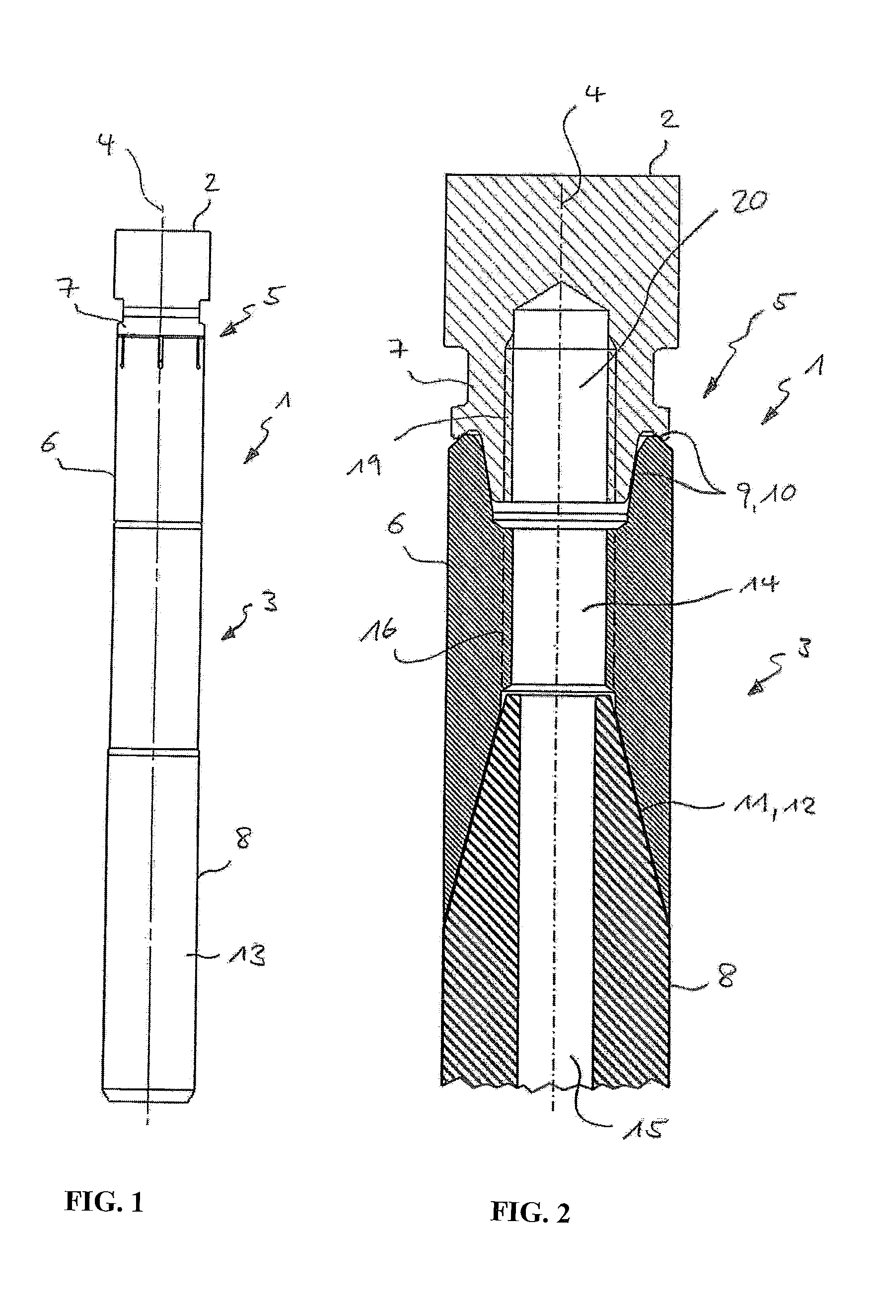
[0020]One of the interface parts or both interface parts can be joined to the respective tool part, i.e. to the tool head or to the tool shank, so as to constitute a single piece therewith. Alternatively, each of the interface parts can also be produced as a separate part and joined to the respective tool part. In particular, in a preferred embodiment of the design, the shank-side interface part is a separate part. In this case, the tool shank is a multipart tool shank and comprises, in addition to the shank-side interface part, a shank body connected thereto. This makes it possible, in particular, for the shank body and the shank-side interface part to be produced from differing materials.

