
Process and System for Manufacturing a Customized Orthosis

a technology for orthotics and manufacturing processes, applied in the field of customized orthotics, can solve the problems of unsatisfactory shape characteristics such as component curvatures and joint alignment, manual manufacturing, undesirable variability,

Inactive Publication Date: 2011-04-07
UNIVERSITY OF DELAWARE
View PDF9 Cites 41 Cited by
  • Summary
  • Abstract
  • Description
  • Claims
  • Application Information

AI Technical Summary

Benefits of technology

[0025]FIGS. 6A and 6B depict exemplary intra-component dimensions measured during a dimensional accuracy assessment step;

Problems solved by technology

While manual manufacturing methods can sufficiently generate a PD-AFO with customized size, augmented shape, and functional characteristics, manual manufacturing methods can contribute to undesirable variability in quality or effectiveness of manufactured components, depending on an orthotists' skill and experience, and may require substantial time and expertise to ultimately manufacture orthoses having functional characteristics that match the unique gait dynamics of each patient.
Additionally, while this method can sufficiently generate a PD-AFO with customized size characteristics, shape characteristics such as component curvatures and joint alignment cannot be precisely tuned.
Furthermore, the position of the ankle joint is fixed at the time of casting and thus clinical joint alignments cannot be made during the fabrication process.
The cost of such customized devices is also substantial.
While this CAD model was parameterized for size and ankle angle, the orthosis design lacked the organic shape characteristics and parameterization of orthosis functional characteristics.

Method used


Image

  • Process and System for Manufacturing a Customized Orthosis
  • Process and System for Manufacturing a Customized Orthosis
  • Process and System for Manufacturing a Customized Orthosis

Examples


example

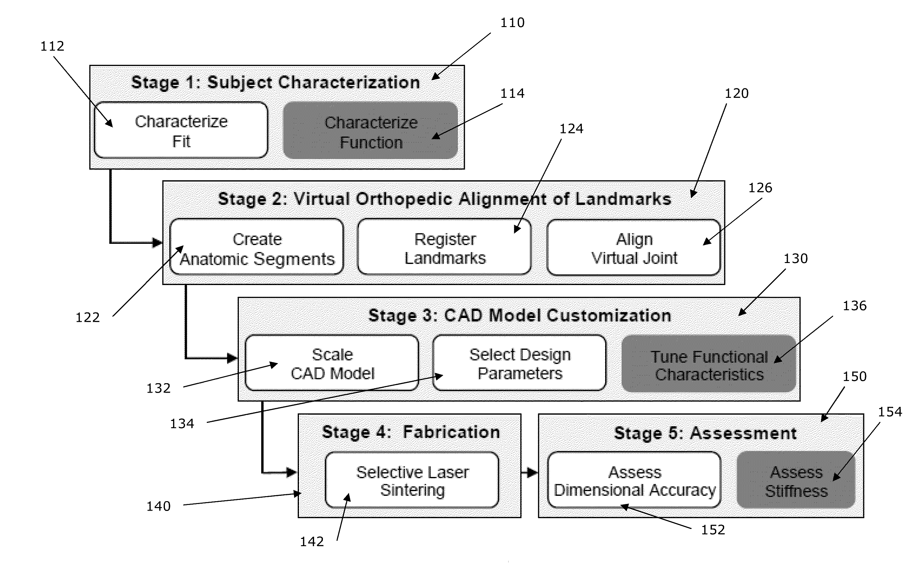
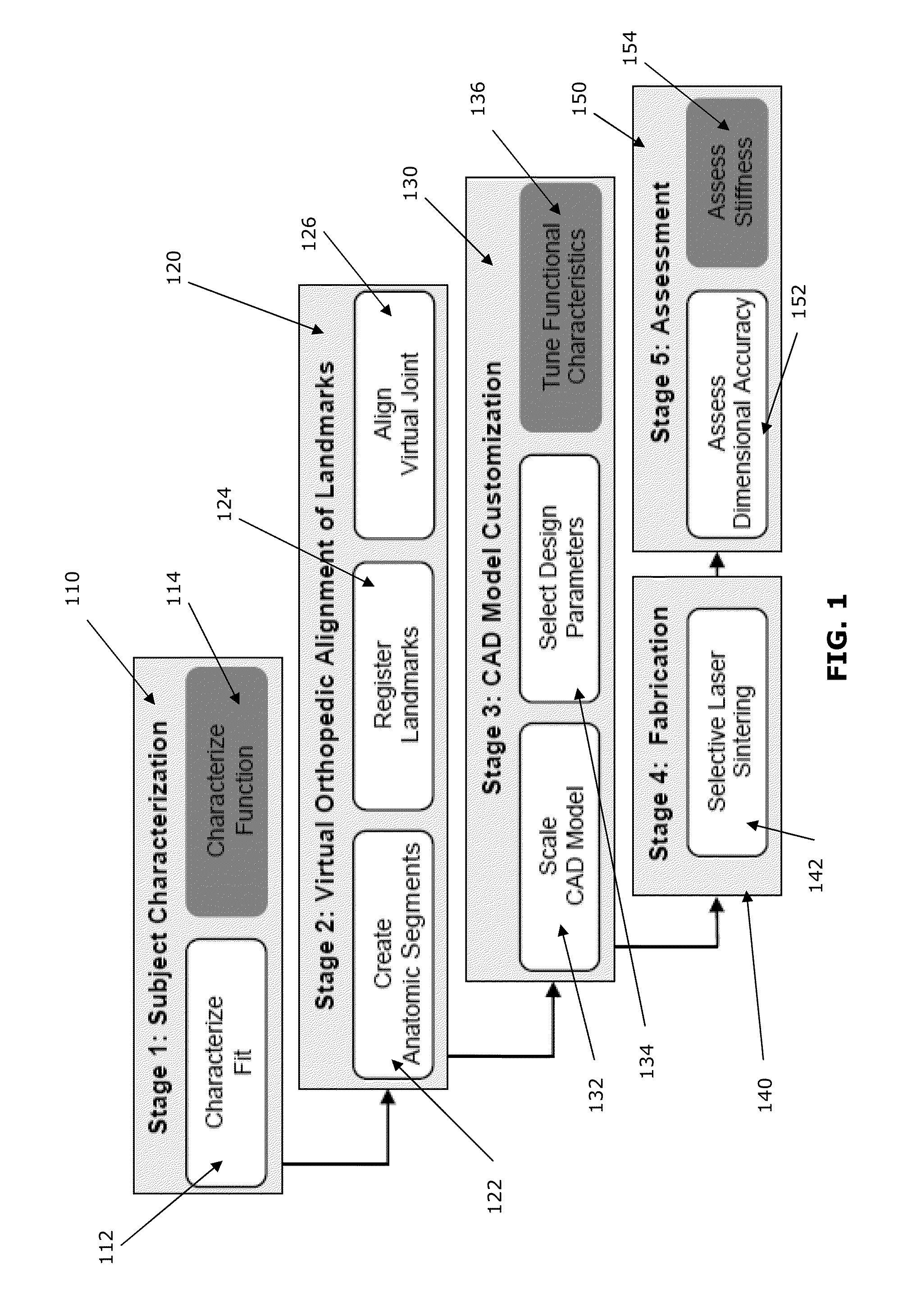
[0056]In one example 3D digitized landmark data were obtained from the right lower extremity of two subjects: one healthy male subject (age 48 years; height 1.77 m; mass 71.8 kg) and one healthy female subject (age 21 years; height 1.65 m; mass 59.9 kg). Each of the subjects underwent the process described above.

[0057]All four PD-AFOs were fabricated in a single build in an SLS Vanguard HS machine with stable temperature control using DuraForm® EX Natural Plastic (3DSystems, Rock Hill, S.C., USA). Manufacturer-indicated build settings were used, and scale factors were determined using industry standard techniques to account for part shrinkage. In a separate build, two full-scale PD-AFOs were fabricated and stiffness tuned to 50% of the subjects' natural pseudo-ankle-stiffness to enable subjective assessment of the fit customization by the subjects during PD-AFO use.

[0058]Three-dimensional distances for the intra- and inter-component dimensions obtained from the PD-AFO CAD model rang...


PUM


Abstract

A process and system for fitting, customizing and manufacturing an orthosis for a subject. 3-dimensional coordinates for a plurality of landmarks corresponding to anatomical characteristics of the subject, means for attachment of the orthosis to the subject, and a reference plane are digitally acquired. Then, coordinates of one or more virtual landmarks corresponding to one or more anatomical joint centers or joint projection locations are calculated. The landmarks are clinically aligned in a reference position of one of the anatomical joint centers and a customized digital model of the orthosis is created using the clinically aligned landmarks. Finally, the orthosis is fabricated using a computer aided manufacturing process, based upon an output from the customized digital model.

Description

CROSS REFERENCE TO RELATED APPLICATIONS[0001]This application claims priority to U.S. Provisional Application Ser. No. 61 / 241,608, filed Sep. 11, 2009, which is incorporated herein, in its entirety, by reference.BACKGROUND OF THE INVENTION[0002]According to the 2005 Americans with Disabilities report, approximately 27 million people over the age of 15 had a walking-related disability. Ankle joint musculature plays an extremely important role during walking and is thought to be the primary muscle group that supports upright stance and produces forward propulsion. Individuals with muscular weakness about the ankle, an impairment often caused by upper motor neuron disorders and lower extremity injuries, are frequently prescribed ankle-foot orthoses (AFOs), which brace the ankle during gait and aim to improve gait function.[0003]Passive-dynamic ankle-foot orthoses (PD-AFOs) constitute one class of ankle braces that rely on material properties and physical features to establish functiona...

Claims


Application Information

Patent Timeline
Patent Type & Authority Applications(United States)
IPC IPC(8): G06F19/00
CPCG01B5/008G06F17/50G06T2210/41G06T19/00B33Y50/00G06F30/00
Inventor STANHOPE, STEVEN J.SCHRANK, ELISA
Owner UNIVERSITY OF DELAWARE
Learn More