Finite element modeling method based on real material microstructure

A technology of microstructure and modeling methods, applied in 3D modeling, image data processing, instruments, etc., can solve problems such as unacceptable, achieve the effect of suppressing noise, saving programming process, and improving reliability

Inactive Publication Date: 2014-09-24
XIANGTAN UNIV
View PDF6 Cites 21 Cited by
  • Summary
  • Abstract
  • Description
  • Claims
  • Application Information

AI Technical Summary

Problems solved by technology

[0005] Some scholars also use computer programming technology to combine the basic knowledge of digital image processing and computer language to express the microstructure of materials in finite elements. However, the realization of this method requires the support of strong computer programming technology knowledge, which undoubtedly creates a threshold. This method is difficult to be accepted by most people

Method used


Image

  • Finite element modeling method based on real material microstructure
  • Finite element modeling method based on real material microstructure
  • Finite element modeling method based on real material microstructure

Examples


Embodiment Construction

[0047] The present invention will be described in detail below in conjunction with the accompanying drawings and embodiments.

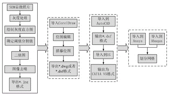
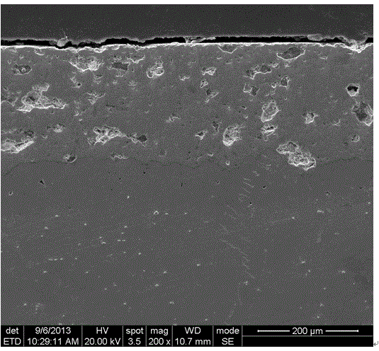
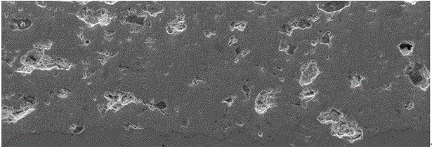
[0048] The present invention belongs to the pre-processing part of finite element modeling, combines digital image processing technology, and the technology of converting bitmap into vector diagram. On the basis of the real microstructure of the material, the microvoids and inclusions in the material structure are represented in the numerical simulation. The main auxiliary software used are: Photoshop, CorelDraw, AutoCAD, UG, Ansys, ABAQUS, etc. The present invention skips the tedious programming process and directly operates on the basis of the existing mature software. The operation is simple and easy to be accepted by beginners. The following is an analysis of the APS-TBCs (thermal barrier coating) materials coated on the turbine blades of aerospace engines.

[0049] During the production process of APS-TBCs (plasma sprayed thermal barrier coatings...


PUM


Abstract

The invention provides a finite element modeling method based on a real material microstructure. According to the method, various kinds of digital image technical processing are carried out on SEM scanned pictures, conversion from bitmaps to vector diagrams is achieved, and accordingly the real material microstructure can be mapped into a two-dimensional finite element model. By means of threshold segmentation, gray processing, binarization processing, repeated switch-off and switch-on operations and the technology converting the bitmaps into the vector diagrams, defects presented in the images or reinforcements are clearly segmented from a substrate, and besides attributes of the defects or the reinforcements can be respectively defined in finite element software. According to the method, a high-precision finite element model of the real material microstructure is built directly through the SEM pictures, a digital model is close to a real structure, and authenticity of the finite element model in the calculation process and in calculation results is improved. The method can be widely used in the field of optimization design field taking the defects and heterogeneous material performance judgment into consideration.

Description

technical field [0001] The invention belongs to the technical field of finite element modeling with many defects or multi-phase materials. Background technique [0002] During the production process of the workpiece, either actively or passively, inclusions or defects will always be introduced into the structural organization, such as shrinkage cavities generated during the casting process, inclusions in dispersion strengthening, which will affect the performance of the product have a decisive role. In exploring the performance of materials, we often use the method of finite element modeling to analyze its performance and damage under various loading conditions, and the existence of various defects or inclusions has a huge impact on its performance Therefore, how to establish a finite element model close to reality is extremely important. [0003] The traditional finite element modeling method is limited to the finite element software itself, and only artificially construc...

Claims


Application Information

Patent Timeline
Patent Type & Authority Applications(China)
IPC IPC(8): G06T17/30G06T5/00G06T7/00
Inventor 杨丽董杰周益春蔡灿英
Owner XIANGTAN UNIV
Why Eureka
Try Eureka