Method for ascertaining a rotational direction of a rotating body, and wheel sensor module

a technology of rotating bodies and sensors, applied in the direction of instruments, devices using electric/magnetic means, transportation and packaging, etc., can solve the problems of complicated and costly, and achieve the effect of preventing completely or largely the transmission of erroneous data and great precision

Active Publication Date: 2011-04-07
ROBERT BOSCH GMBH
View PDF1 Cites 41 Cited by
  • Summary
  • Abstract
  • Description
  • Claims
  • Application Information

AI Technical Summary

Benefits of technology

[0012]Thus a verification of the rotational direction is possible from multiple measurements, where not only the particular rotational directions themselves ascertained in the measurements, but also the rotational speeds ascertained at the same time are used. According to the present invention, this makes greater precision and thus reliability poss

Problems solved by technology

Placing two sensor devices on the wheel with a 90° phase shift makes it possible to obtain pure tangential acceler

Method used


Image

  • Method for ascertaining a rotational direction of a rotating body, and wheel sensor module
  • Method for ascertaining a rotational direction of a rotating body, and wheel sensor module
  • Method for ascertaining a rotational direction of a rotating body, and wheel sensor module

Examples


implementation example 1

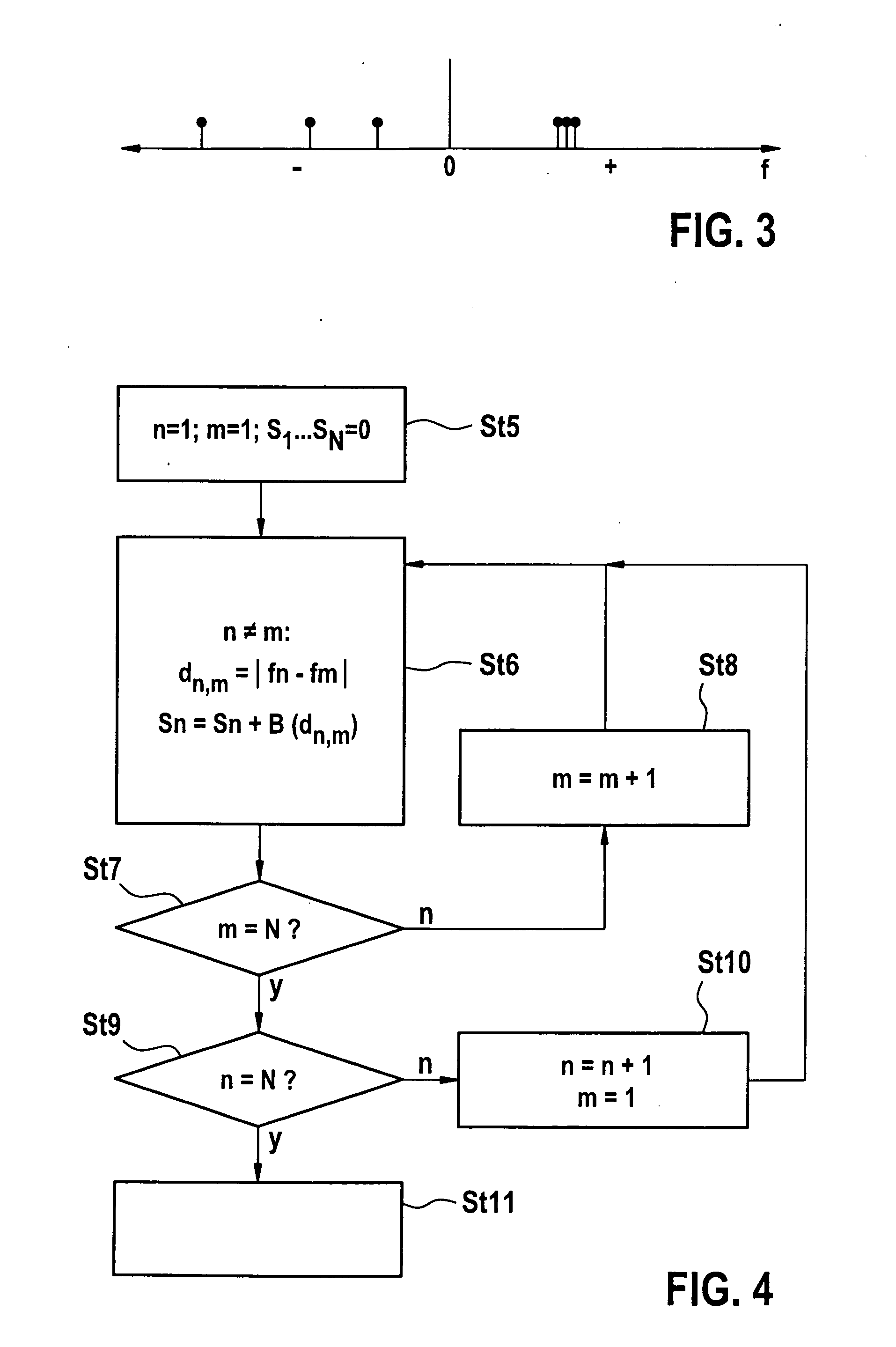
[0046]The best of the measured rotational frequencies fi is ascertained. This may be done in particular through statistical analysis or weighting. According to the example shown in FIG. 4, it is possible in particular for each ascertained frequency fn=ωn / (2π) to determine the magnitude dn,m of the difference from the other m calculated frequencies of the other measuring points. Each distance or difference dn,m is advantageously evaluated with rating points on the basis of a rating function B(dn,m). For example, a difference dn,mn,m2 Hz with 0 rating points. For each frequency fn, the sum Sn of all rating points of the differences from the other frequencies is ascertained, i.e.

Sn=∑mB(dnm)

[0047]Then rotational frequency fn having the highest sum Sn is ascertained. On the basis of the height of Sn, it is possible in addition to estimate the probability of whether this frequency is actually correct; furthermore, a minimum value for Sn may be established, so that Sn must reach or exceed ...

implementation example 2

[0050]This implementation according to FIG. 5 is similar in principle to the first implementation example of FIG. 4; however the calculated frequencies are not rated with points, but rather in step St12 the entire relevant frequency spectrum is discretized, i.e., broken down into discrete frequency ranges fdi for i=1 to Z. Next, in step St13 all discretized frequencies fdi are rated with rating points of at least one rating function B(fdi), which may correspond for example to the function described above in reference to FIG. 4 or may have a different weighting. Then in step St14 the discretized frequency fdi whose sum Si has the highest value is ascertained to be the best. Thus with this implementation example, contrary to the first implementation example described above, it is also possible to ascertain as the best frequency a frequency fdi that was not calculated in one of the measurements.

[0051]FIG. 6 shows the first implementation example of FIG. 4 in the upper diagram a and the...


PUM


Abstract

In a method for ascertaining a rotational direction of a rotating body, one rotational direction and one rotational speed value which indicates the rotational frequency of the rotating body are ascertained in each of multiple measurements. The rotational speed values of the multiple measurements are compared to each other, and a rotational direction of the rotating body is ascertained from the measured rotational directions and the comparison of the rotational speed values.

Description

BACKGROUND OF THE INVENTION[0001]1. Field of the Invention[0002]The present invention relates to a method for verifying, or checking the plausibility of, a rotational direction of a rotating body, e.g., a vehicle wheel or of a shaft.[0003]2. Description of the Related Art[0004]The utilization of acceleration sensors is known for ascertaining the rotational direction and / or rotational speed of rotating or turning systems. In particular, wheel sensor modules which detect different measured variables are utilized in vehicle wheels, for example the tire air pressure, a temperature and the accelerations themselves, and communicate these measured variables or part of these measured variables via a transmitting device to a receiver on the vehicle body. In some cases it is provided that the wheel sensor modules themselves do not receive any data with locating information, and also that no data are sent by the vehicle in such a way that their position on the vehicle is recognizable from the ...

Claims


Application Information

Patent Timeline
IPC IPC(8): G06F15/00G01P3/42G01P15/00
CPCB60C23/0416G01P13/04G01P3/22
Inventor GEISLER, DOMINIKWENZLER, AXELBROCKMANN, MARKUS
Owner ROBERT BOSCH GMBH
Why Eureka
Try Eureka