Footwear with heating arrangement

a technology of heating arrangement and footwear, applied in the field of footwear, can solve the problems of not being able to maintain the predetermined temperature on the sole, the size of the rechargeable battery which can be received in the sole is therefore also limited, and the rechargeable battery has merely limited capacity,

Inactive Publication Date: 2011-04-14
LUO DANXIA
View PDF7 Cites 31 Cited by
  • Summary
  • Abstract
  • Description
  • Claims
  • Application Information

AI Technical Summary

Benefits of technology

[0009]Another advantage of the invention is to provide footwear, comprising a footwear sole; a footwear vamp provided on top of said footwear sole; and a heating arrangement, which comprises a rechargeable battery; a control circuitry comprising a switching circuitry and a status indicator circuitry electrically connected with said switching circuitry, a control outlet, an intelligence control circuitry electrically connected with said switching circuitry, a thermistor, and a power control circuitry electrically connected with said control outlet, and comprises a voltage maintenance circuitry, wherein said intelligence control circuitry is electrically connected with said thermistor; a heater element electrically connected with said control circuitry; a heater switch; and a recharging inlet, wherein said heater element is controlled by said control circuitry to selectively generate heat for maintaining a predetermined temperature at said footwear sole.
[0010]The heater element mentioned above comprises an infrared heating unit provided on the sole of the footwear for generating heat in the vicinity of Yongquan acupuncture point of the wearer. The intelligence control circuitry comprises an infrared control circuitry.
[0011]The infrared heating unit as mentioned above comprises an infrared filament which comprises carbon or tungsten wire, or any other kinds of heating films.
[0012]The footwear sole of the footwear mentioned above further comprises an insole, wherein the heater element is received underneath the insole.
[0013]The footwear sole of the footwear mentioned above further comprises an outsole, wherein the heater switch and the recharging inlet are provided on the outsole.
[0014]The footwear mentioned above further comprises a switch comprising a back panel, a front panel operatively coupled with the back panel, and a switch member provided on the front panel, wherein a recharging inlet is provided on the front panel. The front panel and the back panel are alignedly attached on an outer side and an inner side of the vamp respectively.

Problems solved by technology

First, since the sole of the conventional shoe has limited space, the size of the rechargeable battery which can be received in the sole is therefore also limited.
Thus, the rechargeable battery has merely limited capacity and needs recharging very frequently.
When the heater unit is out of battery while the wearer is away from recharging facility, the shoe, even if equipped with the heater unit, is identical to traditional shoe and cannot maintain the predetermined temperature on the sole.
In other words, conventional heater units for footwear can only work for a very limited period of time.
Second, the conventional shoe mentioned above can only be recharged through a recharging inlet which is usually located at either side of the vamp or the outsole of the shoe, the recharging inlet is likely to be in contact with dirt, dusts or even liquid when the shoe is worn by the user who engages in outdoor or even indoor activities.
This may damage the recharging inlet and therefore undesirably prevent the heater unit from being properly recharged.

Method used


Image

  • Footwear with heating arrangement
  • Footwear with heating arrangement
  • Footwear with heating arrangement

Examples


Embodiment Construction

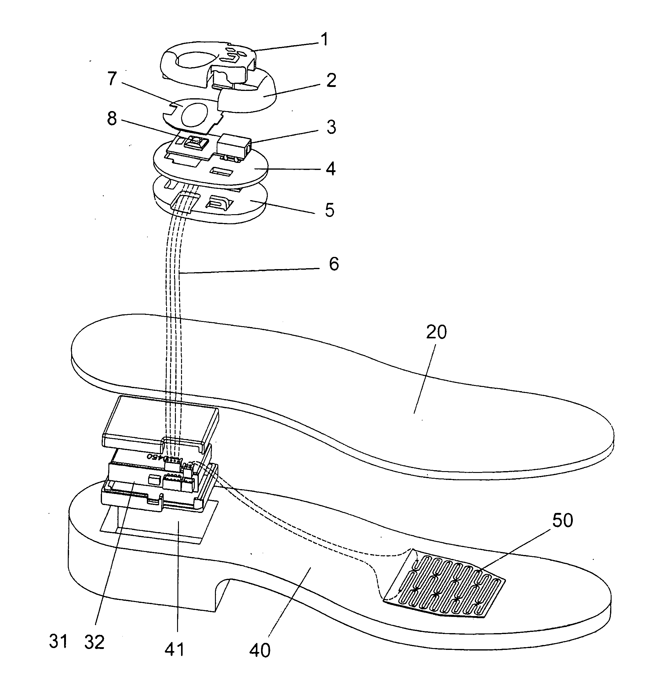
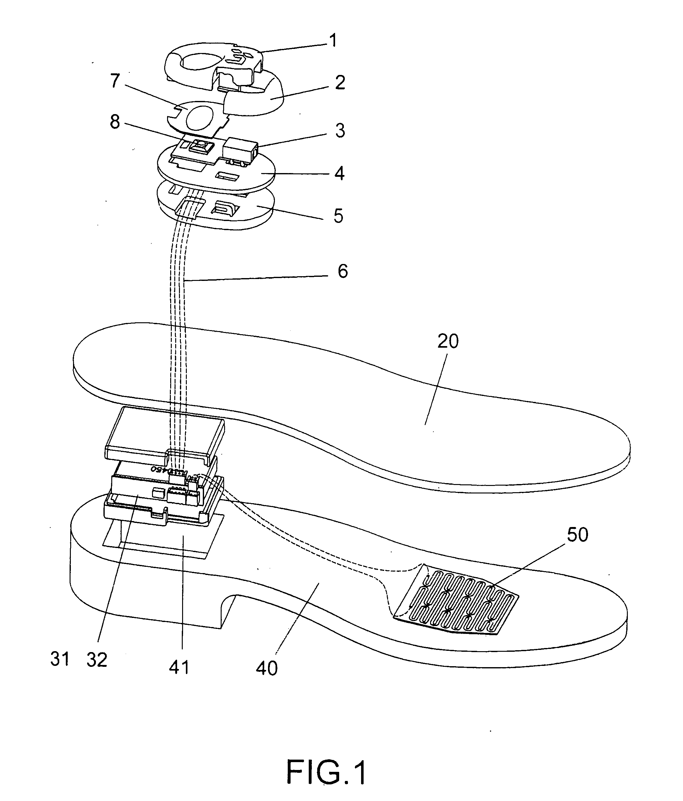
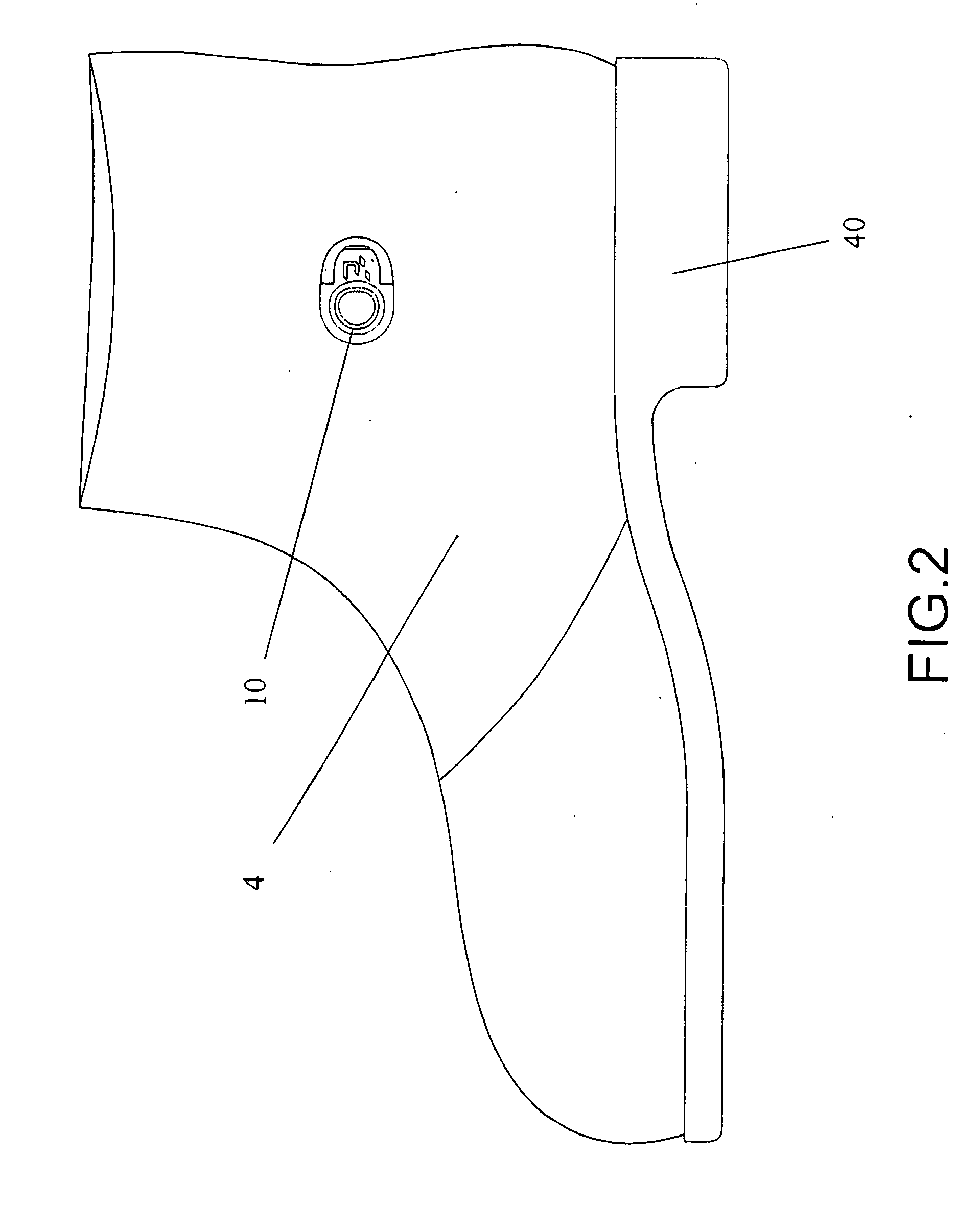
[0024]Referring to FIG. 1 to FIG. 2 of the drawings, a kind of footwear according to a preferred embodiment of the present invention is illustrated, in which the footwear, such as a shoe, comprises a footwear sole comprising an outsole 40, a footwear vamp 4, a heating arrangement comprising a rechargeable battery 31 received in the footwear sole, a control circuitry 32, a heater element 50, a switch 10 and a recharging inlet 3, wherein the heater element 50 is electrically connected to a thermistor in series.

[0025]Referring to FIG. 3 and FIG. 4 in the drawings, the control circuitry 32 comprises a status indictor circuitry 100, a switching circuitry 200, an intelligence control circuitry 300, a power control circuitry 400, a control outlet 500, wherein the power control circuitry 400 comprises a voltage maintenance circuitry. The status indicator circuitry 100 comprises a LED, wherein the status indicator circuitry 100 is electrically connected with the intelligence control circuitr...


PUM


Abstract

A footwear which includes a footwear sole, a footwear vamp, and a heating arrangement, wherein the heating arrangement includes a rechargeable battery, a control circuitry, a heater element, a heater switch, and a recharging inlet, wherein the control circuitry includes a switching circuitry and a status indicator circuitry electrically connected with the switching circuitry, a control outlet, an intelligence control circuitry electrically connected with the switching circuitry, a thermistor, and a power control circuitry electrically connected with the control outlet. The power control circuitry includes a voltage maintenance circuitry, wherein the intelligence control circuitry is electrically connected with the thermistor. The heater element is electrically connected with the control circuitry, and is controlled by the control circuitry to selectively generate heat for maintaining a predetermined temperature at the footwear sole.

Description

BACKGROUND OF THE PRESENT INVENTION[0001]1. Field of Invention[0002]The present invention relates to footwear, and more particularly to footwear comprising a heating arrangement which is capable of providing continuous heating to the footwear for an extended period of time.[0003]2. Description of Related Arts[0004]Conventional footwear, such as a conventional shoe, usually comprises a sole a vamp, and a heater unit received in the sole. The heater unit usually comprises a rechargeable battery and a heating element connected to the rechargeable battery to generate heat for maintaining the sole at a predetermined temperature.[0005]This kind of conventional footwear has a number of disadvantages mentioned below.[0006]First, since the sole of the conventional shoe has limited space, the size of the rechargeable battery which can be received in the sole is therefore also limited. Thus, the rechargeable battery has merely limited capacity and needs recharging very frequently. When the hea...

Claims


Application Information

Patent Timeline
Patent Type & Authority Applications(United States)
IPC IPC(8): A43B7/04A43B3/35
CPCA43B7/04A43B3/0005A43B3/35A43B3/34
Inventor LUO, DANXIA
Owner LUO DANXIA
Why Eureka
Try Eureka