
Vibration resistant electric incandescent lamp and method for reducing vibration

Inactive Publication Date: 2011-04-14
GENERAL ELECTRIC CO
View PDF6 Cites 1 Cited by
  • Summary
  • Abstract
  • Description
  • Claims
  • Application Information

AI Technical Summary

Benefits of technology

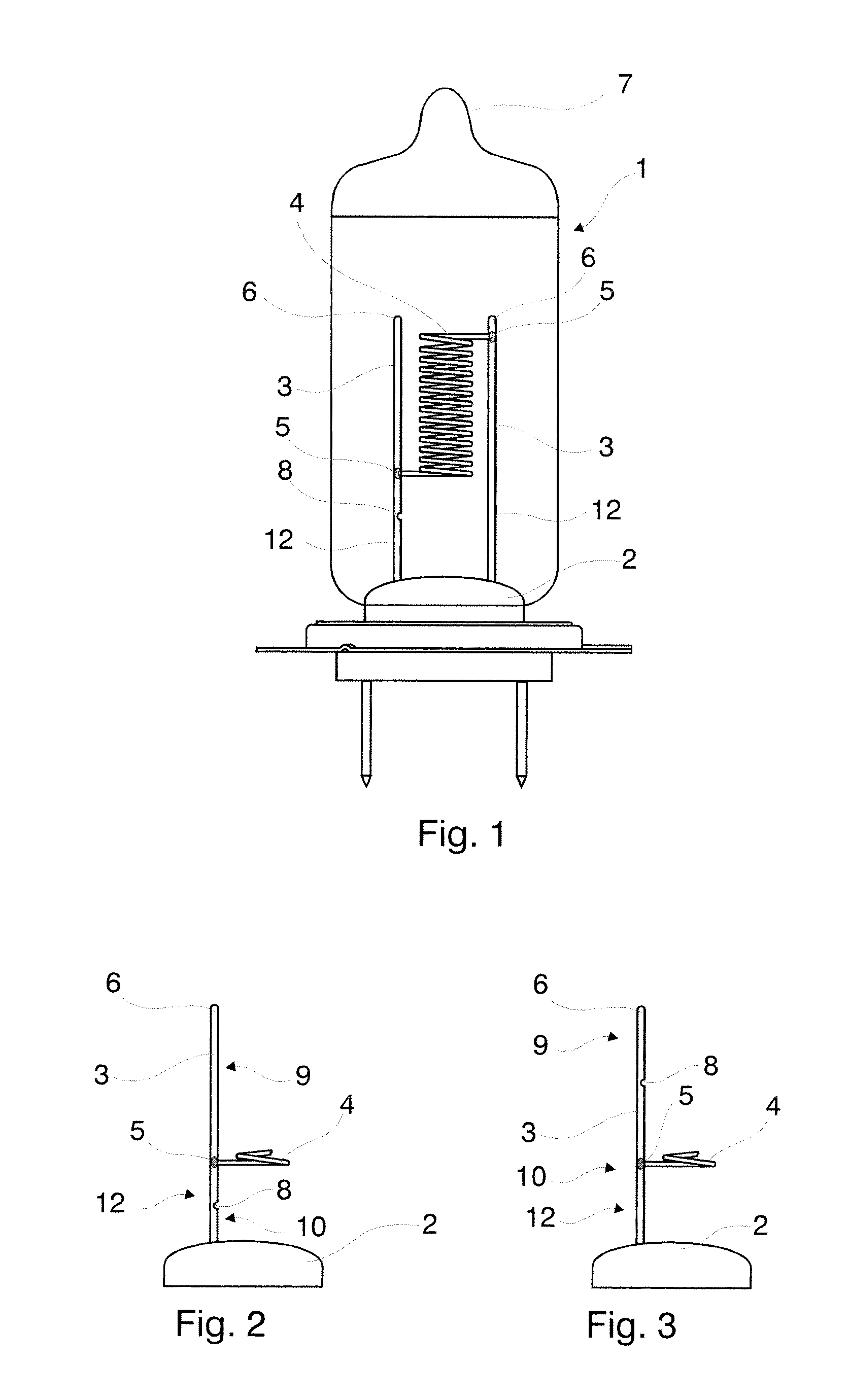
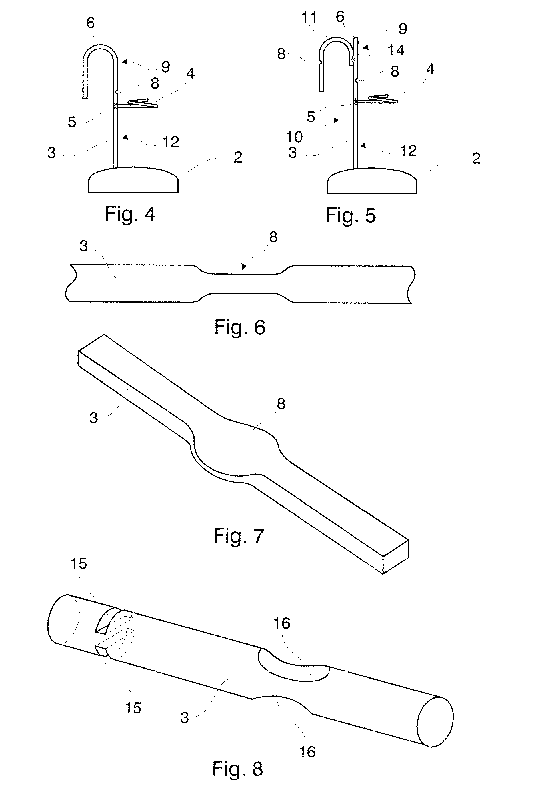
[0009]This invention has several advantages over the prior art. Vibration resistance of the lamp filament is increased without the use of additional element while selecting the dimensions of the narrowed portion properly preserves the mechanical strength of the support wire. The support wire with the narrowed portion itself provides for filtering and damping the vibration of the incandescent filament-support wire system. Positioning of the narrowed portion, adjusting its dimensions and the selection of the number of the narrowed portions offer a broad variety for tuning off the resonant frequency of the filament-support wire system from the outside excitation frequencies causing harmful vibration.

Problems solved by technology

In several technical applications, such as in automotive lamps, the filament structure together with the support wires is subject to shock and vibration.
This shock and vibration may lead to irreversible damage of the filament, especially in cases of resonance.
The additional element, the strut, involves additional manufacturing expenses.
In spite of this, the resulted structure will not be sufficiently resistant to some vibrations that frequently occur in case of headlamps.
The additional strut makes the holder element harder, but its vibration transfer function is worse, due to the harder spring system.

Method used


Image

  • Vibration resistant electric incandescent lamp and method for reducing vibration
  • Vibration resistant electric incandescent lamp and method for reducing vibration
  • Vibration resistant electric incandescent lamp and method for reducing vibration

Examples


Embodiment Construction

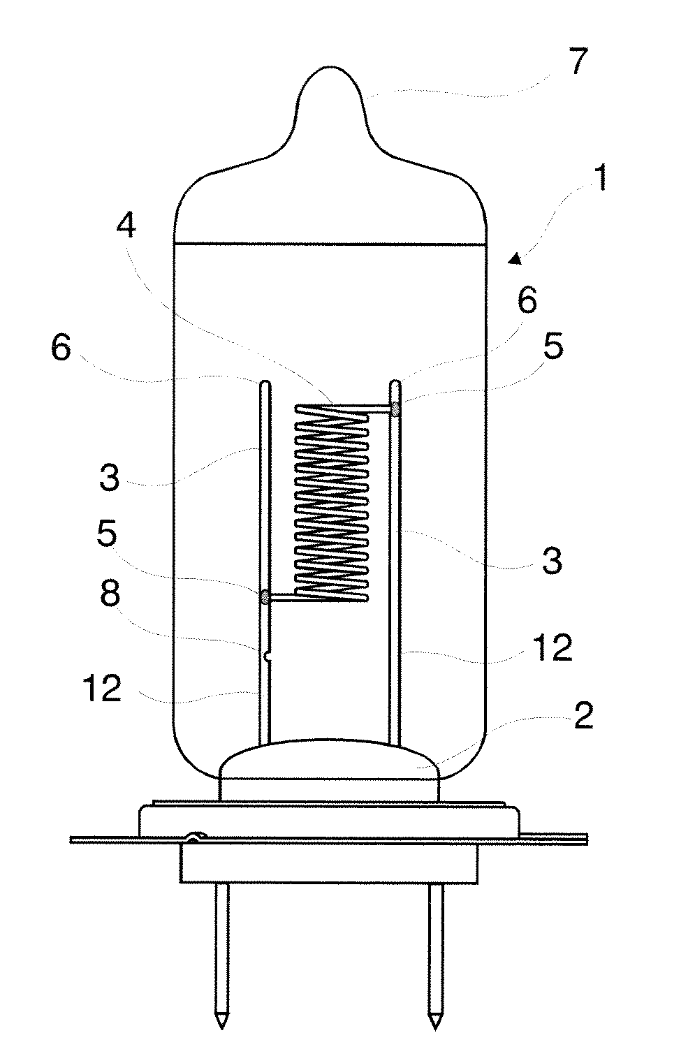
[0019]Referring now to FIG. 1, there is shown an incandescent lamp 1. The lamp 1 has a stem 2 and support wires 3 embedded in and protruding out of the stem 2. The support wires 3 may for example be made of molybdenum or other metals or metal alloys. Material of the stem may be glass. An incandescent filament 4 is fixed to the support wires 3 at end portions of this filament 4. The filament may be made of tungsten. The support wires 3 have a first section 12 extending from the stem 2 to a junction point 5, each end portion of the filament 4 is fixed to a corresponding support wire 3 at its junction point 5. The fixing of the support wires 3 at junction points 5 can be effected by welding, pressing. crimping, or other appropriate manufacturing technology, which provides sufficient mechanical and electrical connection. The junction points 5 of the support wires 3 are not necessarily disposed at their ends. There may be a second section 6 overhanging beyond the junction point 5 viewing...


PUM


Abstract

An electric incandescent lamp comprising at least one incandescent filament is provided. The incandescent filament is arranged inside a translucent envelope. The lamp also comprises support wires that protrude out of a stem. The filament has end portions, and each end portion is fixed to a corresponding support wire at a junction point. At least one of the support wires comprises at least one narrowed portion for reducing vibration. The narrowed portions are disposed between the junction point and the stem. In an exemplary embodiment of another aspect of this invention, at least one of the support wires has a second section overhanging beyond the junction point of the end portion of the filament. The at least one narrowed portion for reducing vibration is comprised by the second section. A method for reducing vibration is also disclosed. This method comprises a step of forming at least one narrowed portion in at least one of the support wires.

Description

BACKGROUND OF THE INVENTION[0001]This invention relates to an electric incandescent lamp that is vibration resistant.[0002]Various electric incandescent lamps known in the art that have quite shock sensitive filament. These lamps have an envelope and a stem within the envelope, and support wires protruding out of the stem. In several technical applications, such as in automotive lamps, the filament structure together with the support wires is subject to shock and vibration. This shock and vibration may lead to irreversible damage of the filament, especially in cases of resonance. In order to avoid the afore-mentioned drawbacks manufacturers tend to strengthen the support wires.[0003]As an example we refer to U.S. Patent Application No. 2006 / 0043898A1. This application relates to an electric incandescent lamp, in particular a vehicle headlight lamp that has an incandescent filament, arranged inside a transparent lamp envelope, and supply leads for the incandescent filament, at least ...

Claims


Application Information

Patent Timeline
IPC IPC(8): H01J19/12
CPCH01K3/08H01K1/18
Inventor TORMA, TAMASMAGAI, ISTVANMAKAI, LASZLOKAPOCS, ZSOLT
Owner GENERAL ELECTRIC CO
Learn More