
Fiber optic adapter plates with integrated fiber optic adapters

a technology adapter plate, which is applied in the field of fiber optic adapter plate, can solve the problems of increased set up time, inconvenient assembly, and inconvenient placement of adapter plate, and achieve the effect of convenient positioning and attaching

Active Publication Date: 2011-04-14
LEVITON MFG
View PDF11 Cites 82 Cited by
  • Summary
  • Abstract
  • Description
  • Claims
  • Application Information

AI Technical Summary

Benefits of technology

The patent describes a new type of fiber optic adapter plate that includes integrated fiber optic adapters. These plates can be made from a rigid or semi-rigid material, like molded plastic or polymer, and can be designed with a color scheme for easy identification. The plates can also have labels molded into them and can be attached to fiber optic enclosures, patch panels, and racks. The patent also describes methods for producing these plates and improvements over conventional fiber optic adapter plates that use discrete adapters. The technical effects of this patent are improved efficiency and ease of use for fiber optic adapter plates.

Problems solved by technology

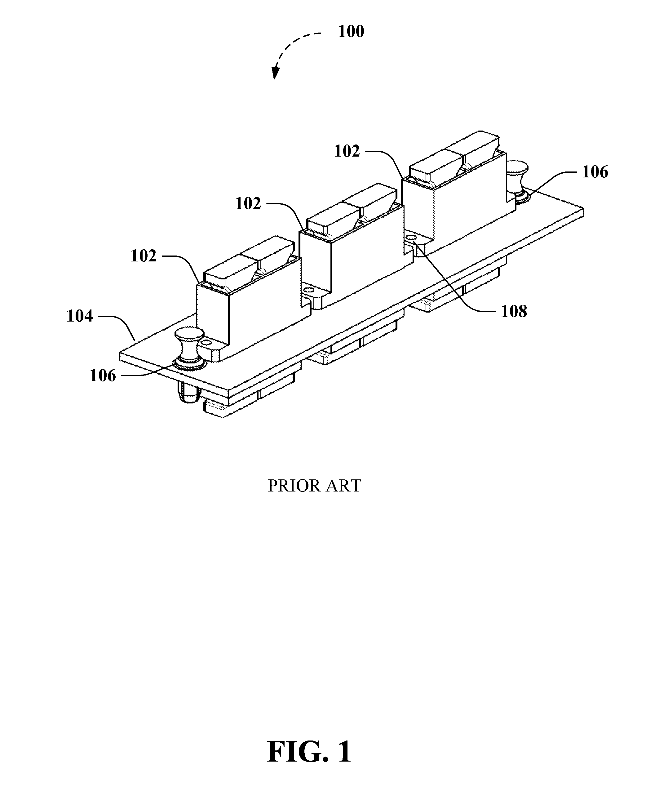
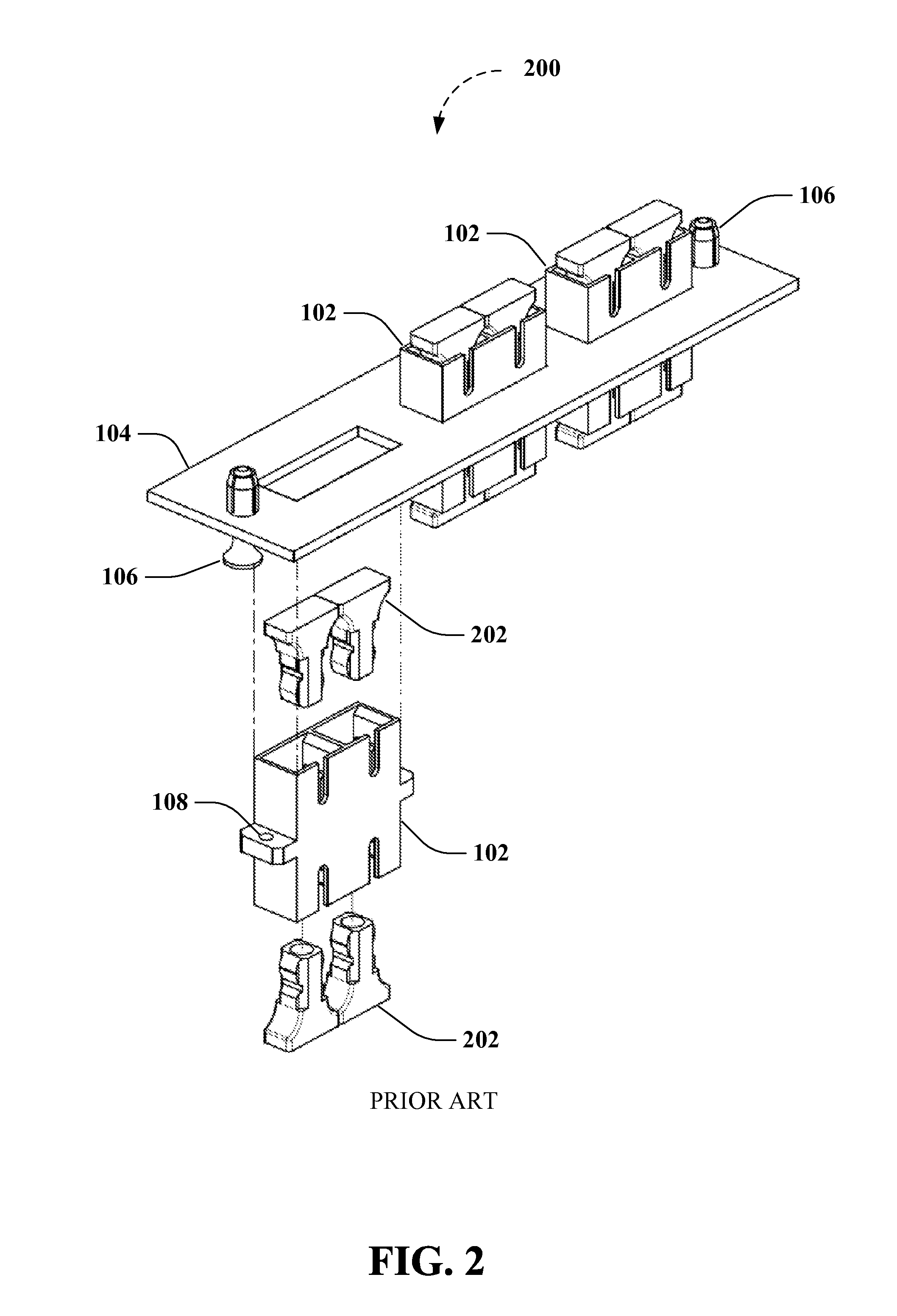
However, such conventional adapter plates suffer from drawbacks due to the assembly of so many discrete parts.
As a result, excessive tolerances can result in additional mechanical play between the adapter and adapter plate which can, in some instances, allow for excessive stresses and bend radii of the connecting fiber optic cables.
As a further example, such conventional assemblies by their nature require costly assembly steps.
However, this can lead to increased set up time, having costs of its own, and can result in end user frustration.
In addition, conventional adapter plate panels are often unlabeled or stamped with labels that are difficult for the end user to ascertain, particularly when the adapter plate is fully outfitted with adapters and cabling.

Method used


Image

  • Fiber optic adapter plates with integrated fiber optic adapters
  • Fiber optic adapter plates with integrated fiber optic adapters
  • Fiber optic adapter plates with integrated fiber optic adapters

Examples


Embodiment Construction

Overview

As used herein, abbreviations are used to denote the following: American National Standards Institute (ANSI); Electronic Industries Alliance (EIA); Fiber Optic Connector Intermateability Standard (FOCIS); Insulated Cable Engineers Association (ICEA); Telecommunications Industry Association (TIA); Standard Connector (SC), also known as Subscriber, Siemens, Snap-in, or Square Connector; Lucent Connector (LC), also known as Little Connector; Physical Contact (PC); Angle-polished Physical Contact (APC); Super-polished Contact (SC); and Ultra-polished Physical Contact (UPC). In addition, as used herein, the terms integrated and integrating are intended to refer to the act of incorporating, forming, or uniting otherwise separate component parts into a whole.

As described herein, various references are made to standards when describing fiber optic connectors and adapters. Such references are made for the purposes of illustration and not limitation. For instance, fiber optic patch co...


PUM

PropertyMeasurementUnit
sizeaaaaaaaaaa
coloraaaaaaaaaa
plasticaaaaaaaaaa

Abstract

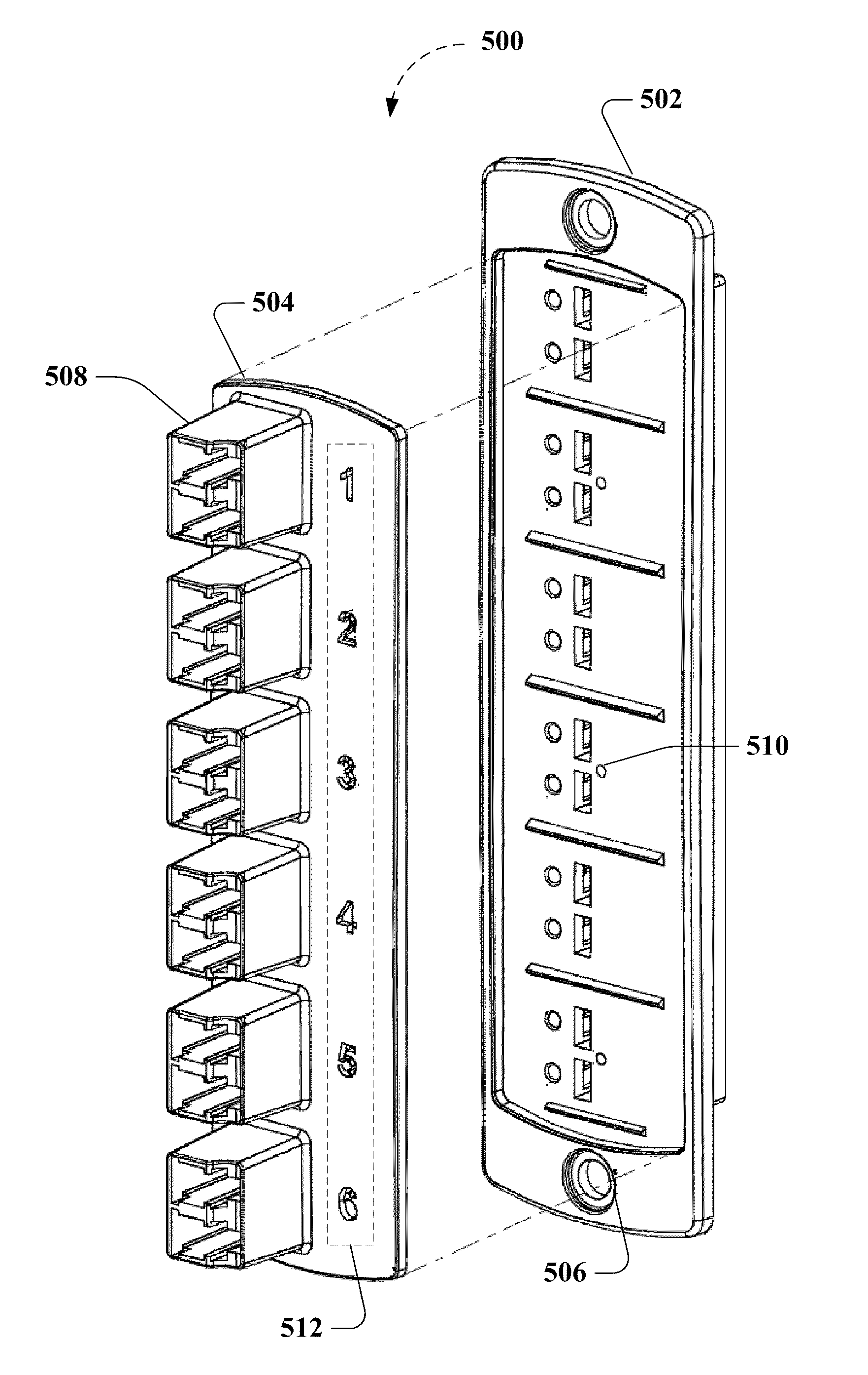
Structures, devices and methods are provided for creating fiber optic adapter plates with integrated fiber optic adapters. In one aspect, fiber optic adapter plates having integrated fiber optic adapter subassemblies are formed from a moldable plastic. For example, a molded plastic fiber optic adapter plate can include a molded plastic adapter back plate having a plurality of integrated fiber optic adapter subassemblies and one or more attachment mechanisms that facilitate locating and attaching an adapter front plate having a corresponding plurality of integrated fiber optic adapter subassemblies on the adapter front plate. Advantages provided by integrating fiber optic adapters into the molded plastic assemblies include superior mechanical strength, manufacturing cost reductions and adapter placement flexibility among other advantages.

Description

FIELD OF THE INVENTIONThe subject disclosure is directed to fiber optic adapter plates and, more specifically, relates to fiber optic adapter plates with integrated fiber optic adapters.BACKGROUND OF THE INVENTIONOptical fiber has been used as a medium for telecommunication and networking because it is flexible and can be bundled as cables. Optical fiber has been especially advantageous for long-distance communications because light propagates through the fiber with little attenuation compared to electrical signals carried by conventional wire cables. Over short distances, such as networking within a building, optical fiber interconnect cables save space in cable ducts because a single fiber can carry more data than a single electrical cable.Interconnect cables are primarily used as intra-equipment jumpers or patch cords. For example, some typical applications include patching active electronics to nearby patch panels, cable cross-connection on distribution frames, and connecting wo...

Claims


Application Information

Patent Timeline
Patent Type & Authority Applications(United States)
IPC IPC(8): G02B6/00B29D11/00
CPCG02B6/3825G02B6/4452G02B6/3897G02B6/3895H04Q1/09G02B6/3865G02B6/3893
Inventor MURPHY, JAMESSAUTER, TOMBORG, LORENEVERETT, MICHAEL
Owner LEVITON MFG
Learn More