Image forming apparatus

a technology of image forming apparatus and forming apparatus, which is applied in the direction of instruments, optics, disinfection, etc., to achieve the effect of increasing the size of the image forming apparatus, efficient removal, and efficient removal

Active Publication Date: 2011-04-14
SHARP KK
View PDF4 Cites 15 Cited by
  • Summary
  • Abstract
  • Description
  • Claims
  • Application Information

AI Technical Summary

Benefits of technology

Furthermore, an exhaust port of the air purifier may be provided at a front surface side wall portion of the main casing of the image forming apparatus. In this case, the air discharged from the exhaust port of the air purifier can spread widely in the room, and airborne microbes in the air can be efficiently removed by the ions contained in this air.
Furthermore, a duct may be provided that protrudes above the image forming apparatus, and an exhaust port of the air purifier that discharges air is connected to the duct to discharge air via the duct to above the image forming apparatus. In this case, the air discharged from the exhaust port of the air purifier can spread widely in the room, and airborne microbes in the air can be efficiently removed by the ions contained in this air.
Furthermore, a paper feeding portion may be arranged at a bottom portion of the image forming apparatus, a paper discharge portion arranged above the paper feeding portion, and a printer portion that is arranged at an intermediate height between the paper feeding portion and the paper discharge portion, and that receives a recording paper from the paper feeding portion and forms an image on the recording paper, then discharges the recording paper to the paper discharge portion, and the air purifier may be arranged below the paper discharge portion. In this case, the air purifier can be arranged below the paper discharge portion. Currently, although the installation space for the air purifier is limited due to the compactness of the image forming apparatus, the above-described configuration easily enables an installation space for the air purifier to be secured below the paper discharge portion.
Furthermore, when the air purifier is arranged below the paper discharge portion, the air purifier is arranged partitioned adjacent to the printer portion, and is easily isolated from the ventilation device arranged near the printer portion. And it is also possible to provide the intake port of the air purifier and the exhaust port of the ventilation device near the wall portions respectively that are opposite each other in the main casing of the image forming apparatus, and the intake port of the air purifier and the exhaust port of the ventilation device can be provided at the wall portions respectively. In this case, it is not necessary to lengthen the air path of the air purifier to ensure the intake port is far from the exhaust port, and it is also unnecessary to increase the size of the air purifier, and thus increases in size of the image forming apparatus can be inhibited.

Problems solved by technology

Furthermore, the intake port of the air purifier that suctions air is provided in a location apart from the exhaust port of the ventilation device, and therefore the air discharged from the exhaust port of the ventilation device, namely air containing exhaust gases of the image forming apparatus, almost never flows to the intake port of the air purifier, and is almost never suctioned into the intake port of the air purifier.

Method used


Image

  • Image forming apparatus
  • Image forming apparatus
  • Image forming apparatus

Examples


second embodiment

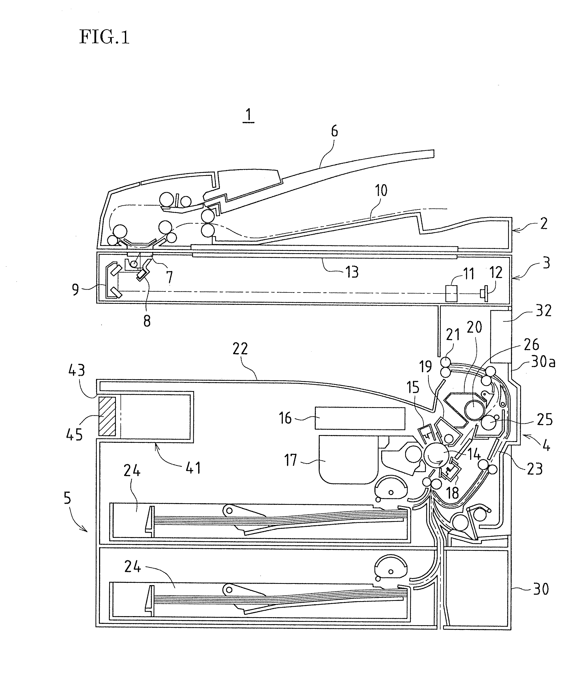
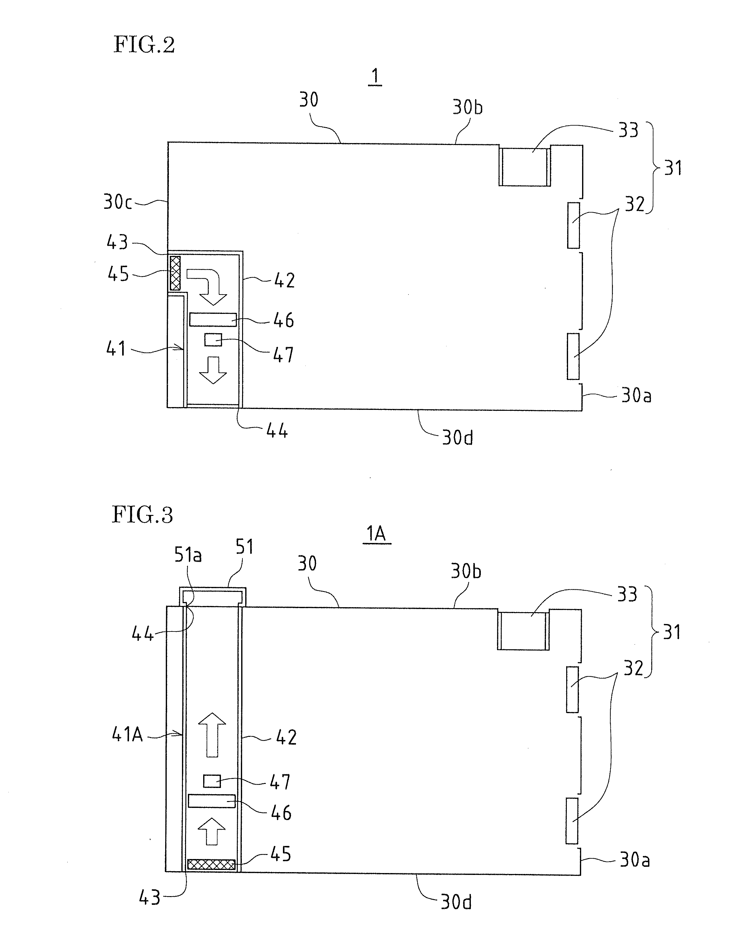
FIG. 3 is a schematic view showing an image forming apparatus according to the present invention as viewed from above. Furthermore, FIG. 4 is a perspective view showing an image forming apparatus according to the present embodiment. Further still, FIG. 5 is a cross-sectional view showing an image forming apparatus according to the present embodiment. It should be noted that in FIGS. 3 to 5, same reference symbols are assigned to portions that fulfill a same function as the apparatus in FIG. 1 and FIG. 2.

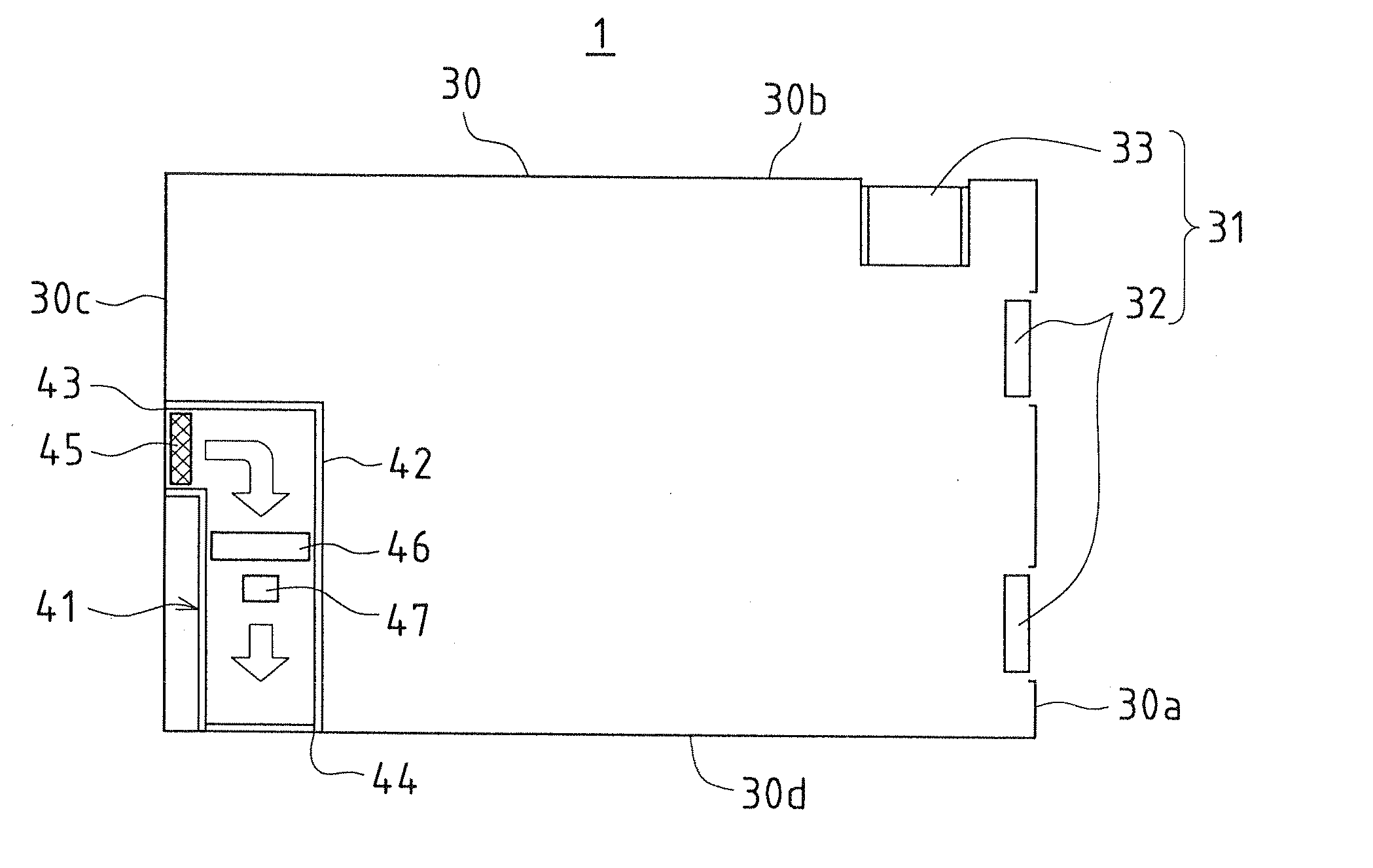
In a same manner as the image forming apparatus 1 of FIG. 1 and FIG. 2, an image forming apparatus 1A according to the present embodiment is provided with the original transport portion 2, the original reading portion 3, the printer portion 4, and the paper feeding portion 5, and the layout thereof is unchanged. Furthermore, the ventilation device 31 is provided and the layout of the exhaust fans 32 and the intake port 33 is also unchanged. However, instead of the air purifier 41 of ...

third embodiment

FIG. 6 is a cross-sectional view that schematically shows an image forming apparatus according to the present invention. It should be noted that in FIG. 6, same reference symbols are assigned to portions that fulfill a same function as the apparatus in FIG. 1 and FIG. 2.

An image forming apparatus 1B according to the present embodiment is a printer that obtains image data received externally, and forms a monochrome image indicated by the image data on a recording paper, and its structure can be broadly divided into a printer portion 4 and a paper feeding portion 5.

The printer portion 4 is arranged above the paper feeding portion 5 and is provided with a photosensitive drum 14, a charging unit 15, an optical scanning unit 16, a developer unit 17, a transfer unit 18, a cleaning unit 19, and a fixing device 20. When a recording paper is transported from the paper feeding portion 5 to the printer portion 4, the recording paper passes between the photosensitive drum 14 and the transfer un...


PUM


Abstract

In an image forming apparatus, exhaust fans of a ventilation device and an intake port of an air purifier are provided on side wall portions respectively that are opposite each other in a main casing of the image forming apparatus, and the exhaust fans of the ventilation device are provided in a location higher than the intake port of the air purifier. With this configuration, silicone that is discharged from the exhaust fans of the ventilation device is almost never suctioned into the intake port of the air purifier, such that almost none of this silicone adheres to a discharging electrode of the ion generator, and an ion generating efficiency of the ion generator can be maintained over a long period without dropping.

Description

BACKGROUND OF THE INVENTIONThis application claims priority under 35 U.S.C. §109(a) on Patent Application No. 2009-235968 filed in Japan on Oct. 13, 2009, the entire contents of which are herein incorporated by reference.The present invention relates to image forming apparatuses such as copiers, printers, and fax machines.Electrophotographic apparatuses are an example of this type of image forming apparatus. In electrophotographic apparatuses, a toner image is formed on a surface of a photosensitive drum by forming an electrostatic latent image on the surface of the photosensitive drum, then developing the electrostatic latent image on the surface of the photosensitive drum using toner, and the toner image is transferred from the photosensitive drum to a recording paper and fixed onto the recording paper by applying heat and pressure to the recording paper.Image forming apparatuses such as these are essential office automation appliances and are installed in most offices, moreover t...

Claims


Application Information

Patent Timeline
Patent Type & Authority Applications(United States)
IPC IPC(8): G03G21/20
CPCA61L9/014G03G21/206A61L2209/14A61L9/22
Inventor AKAGAWA, YUHI
Owner SHARP KK
Why Eureka
Try Eureka