Self-Ligating Bracket for Orthodontics

a self-ligating, orthodontic technology, applied in the field of self-ligating brackets, can solve the problems of difficult to remain within the narrow dimensional tolerances of the bracket body, the difficulty of ensuring the aesthetic appearance of the bracket, and the difficulty of brackets of this type to be manufactured, etc., to achieve the effect of reliable closure and held open

Inactive Publication Date: 2011-04-14
BERNHARD FOERSTER GMBH 75172 PFORZHEIM DE
View PDF11 Cites 32 Cited by
  • Summary
  • Abstract
  • Description
  • Claims
  • Application Information

AI Technical Summary

Benefits of technology

[0008]The object of the present invention is to create a self-ligating bracket that can be made not only of steel, but

Problems solved by technology

The tiny dimensions of the brackets make it difficult to remain within the narrow dimensional tolerances for the bracket body and the sliding element that are required in order for the bracket body, sliding element, and leaf spring to interact properly, in particular to hold the sliding element securely

Method used


Image

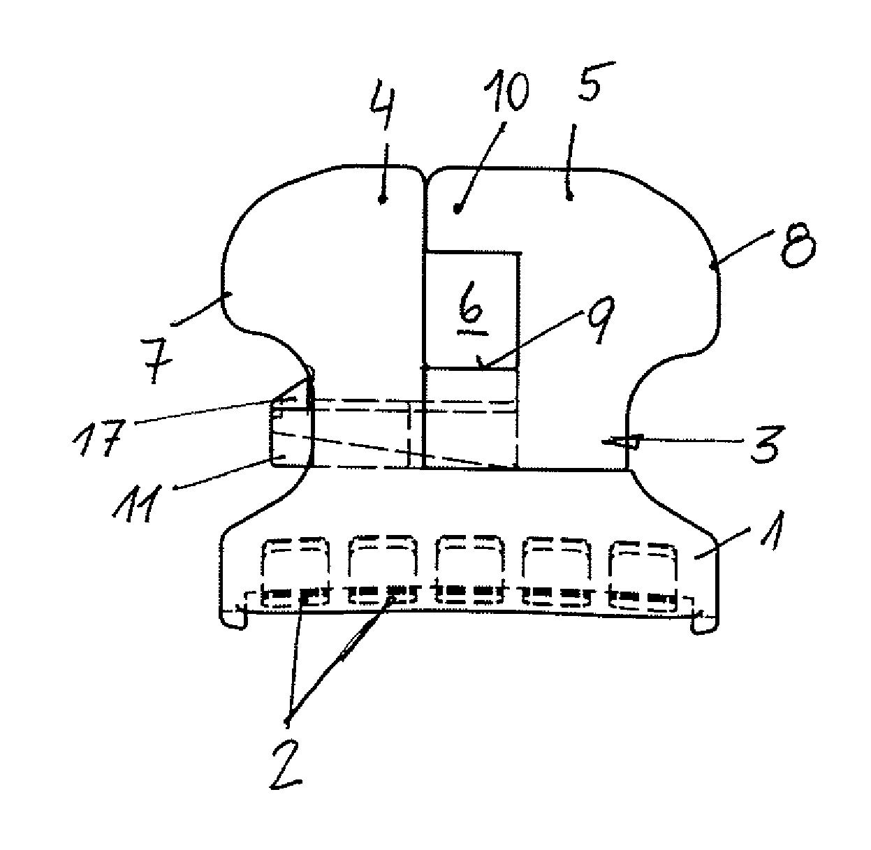
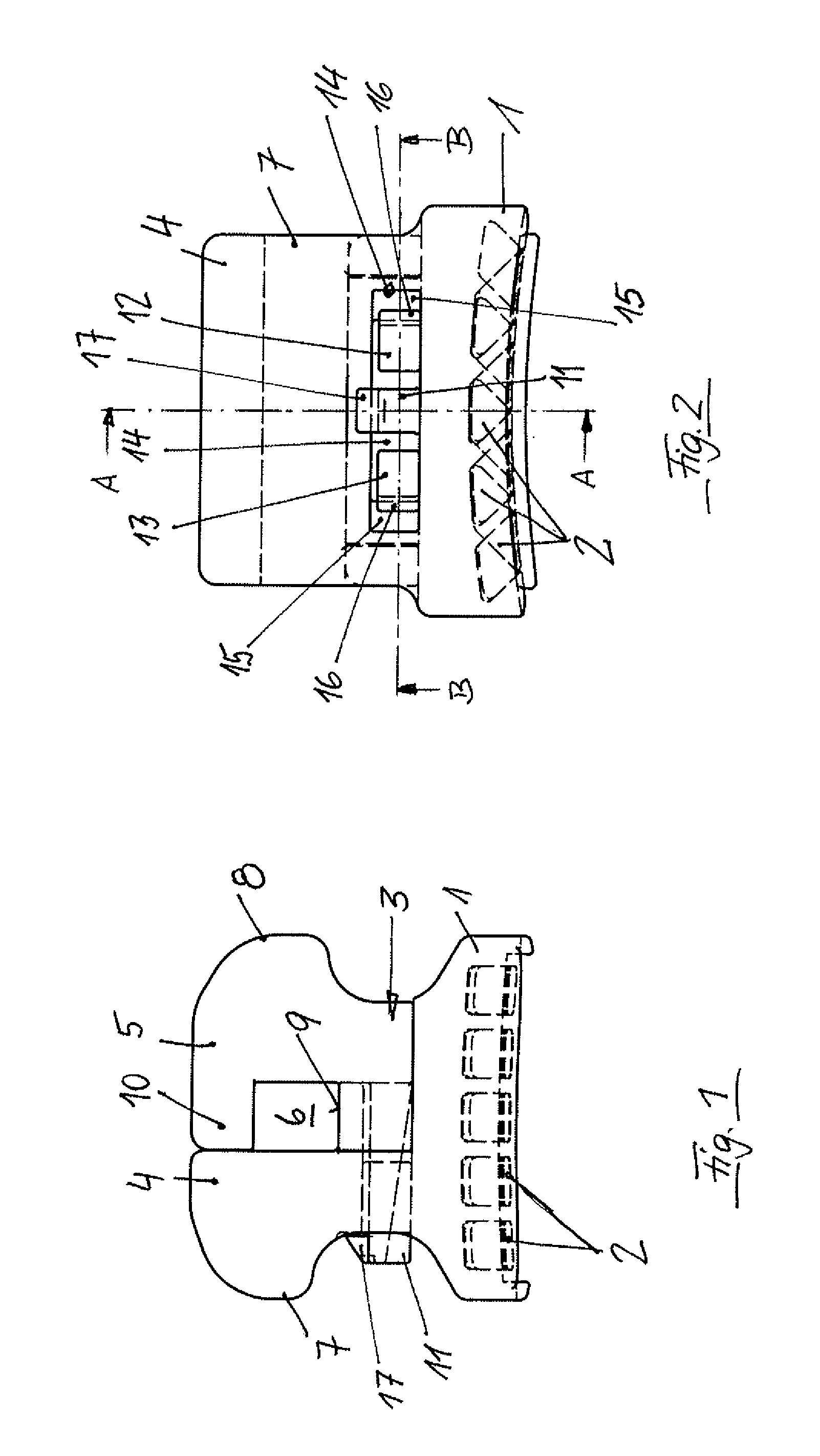
  • Self-Ligating Bracket for Orthodontics
  • Self-Ligating Bracket for Orthodontics
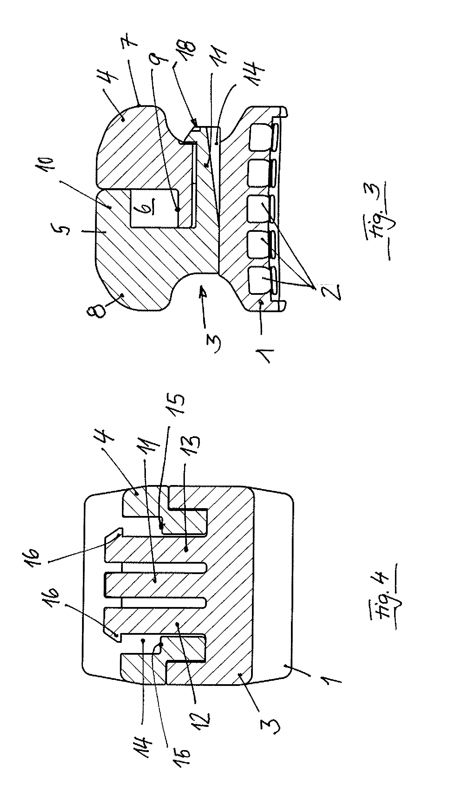
  • Self-Ligating Bracket for Orthodontics

Examples


second embodiment

[0071]Two oblique views of the bracket are depicted in FIGS. 18 and 19.

[0072]The third embodiment of the invention, which is depicted in FIGS. 20 through 25, differs from the first embodiment in that sliding element 3 does not include three parallel arms on its lower end, but rather one wider lingual base 23 which can be displaced in a centrally located slot 14 which extends through gingival wall 4 of the bracket in the gingival-occlusal direction underneath base 9 of channel 6. A recess 25 is provided in lingual surface 24 of slot 14, which is otherwise flat. A leaf spring 26 folded in the shape of a “V” is provided in recess 25 and extends via one leg out of recess 25 and into slot 14. Leaf spring 26 acts on the underside of sliding element 3 which, to this end, includes a flat recess 27 facing base 1, in which two ribs 28 and 29 extending parallel to channel 6 are provided, ribs 28 and 29 tapering in the shape of a wedge in the direction toward base 1. In the closed position of ...

third embodiment

[0074]The third embodiment is particularly advantageous and aesthetic, because the mechanisms used to hold the bracket open and closed are hidden in the bracket. FIGS. 24 and 25 show the closed bracket in two different oblique views. FIGS. 30 and 31 show the open bracket in two different oblique views.

[0075]The fourth embodiment of a bracket, which is depicted in FIGS. 32 through 37, differs from the third embodiment in that a leaf spring folded in the shape of a “V” is not provided in recess 25 in base 1, but rather an elastomeric cylinder 31 is, which performs the same function as spring 26 in the third embodiment.

[0076]In the second, third, and fourth embodiments as well, the components of the bracket—except for leaf spring 26 and the elastomeric cylinder—can be composed either of metal, in particular stainless steel, a plastic e.g. polyoxymethylene (POM), or a ceramic e.g. aluminium oxide or zirconium oxide.


PUM


Abstract

The bracket comprising
  • a bracket body having a base,
  • an occlusal wall extending away from the base and having at least one occlusal ligature wing,
  • a gingival wall extending away from the base and having at least one gingival ligature wing,
  • a channel which extends between the occlusal wall and the gingival wall continuously in the direction from mesial to distal,
  • a sliding element, which is held in a guide of the bracket and can be displaced in the guide, back and forth in the gingival-occlusal direction, between a closed position, in which the channel is closed along at least a portion of its length, and an open position, in which the channel is open in the labial direction,
  • and means that can hold the sliding element in the closed position thereof and, in the open position thereof, captively secure the sliding element, the means being integrated in the bracket.

Description

BACKGROUND OF THE INVENTION[0001]1. Field of the Invention[0002]The invention is directed to a self-ligating bracket having the features indicated in the preamble of claim 1. A bracket of this type is known from DE 10 2006 053 215 A1. It includes a one-pieced bracket body on which a rigid sliding element is disposed in a guide. The sliding element can be displaced back and forth between a closed position, in which it bridges a channel of the bracket, and an open position, in which the channel is open in the labial direction. The sliding element is locked both in the closed position thereof and in the open position thereof using a leaf spring disposed in a slot of the bracket body, which is parallel to the channel, and extends into a recess in the underside of the sliding element.[0003]A bracket of this type is characterized as being self-ligating, because the structure used to secure an archwire in a channel in which it has been placed is an integral component of the bracket, the me...

Claims


Application Information

Patent Timeline
IPC IPC(8): A61C7/14
CPCA61C7/287A61C7/14
Inventor WESSINGER, MICHAEL
Owner BERNHARD FOERSTER GMBH 75172 PFORZHEIM DE
Why Eureka
Try Eureka