Bifurcated highly conformable medical device branch access

Inactive Publication Date: 2011-04-14
WL GORE & ASSOC INC
View PDF26 Cites 120 Cited by
  • Summary
  • Abstract
  • Description
  • Claims
  • Application Information

AI Technical Summary

Benefits of technology

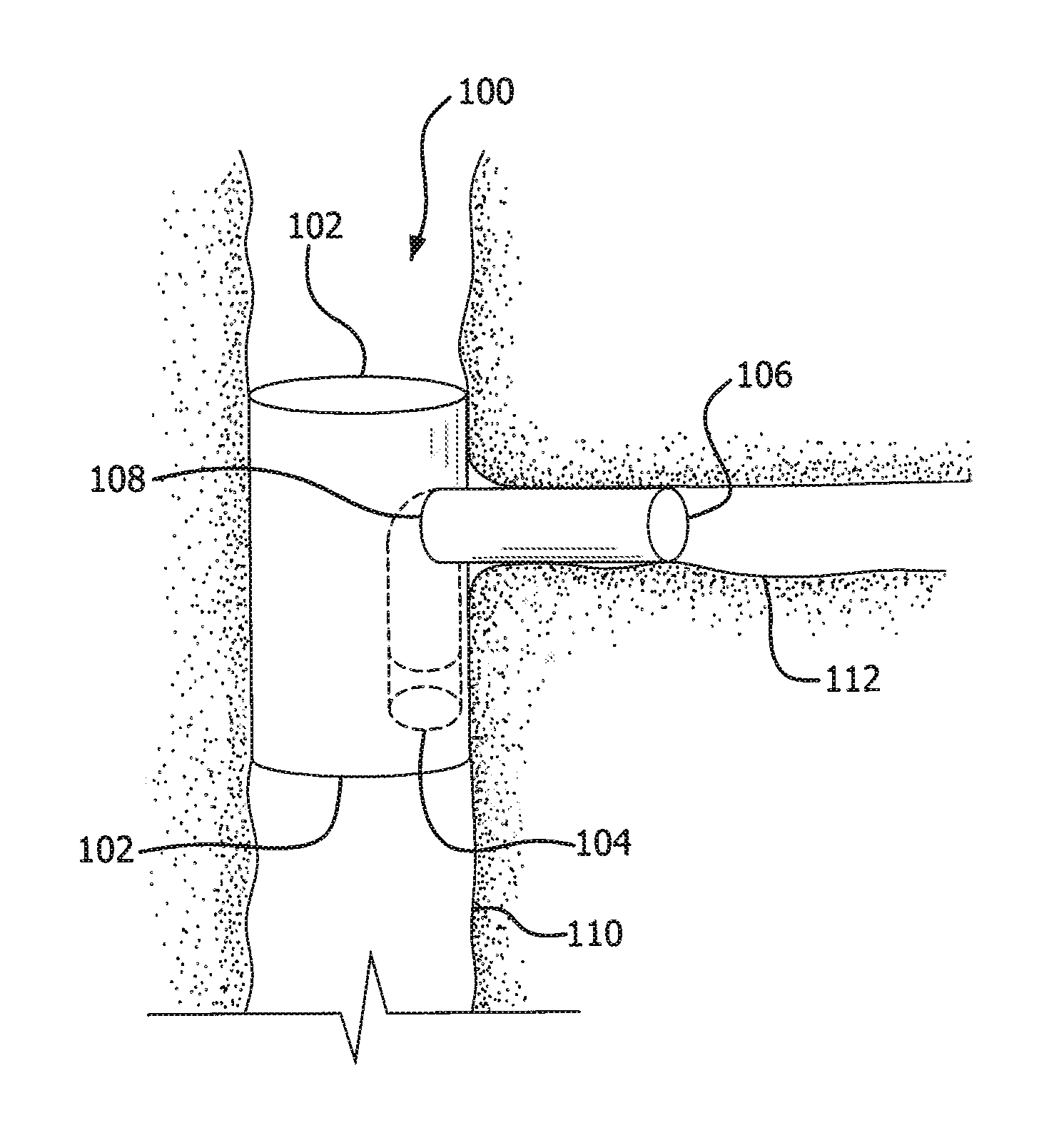
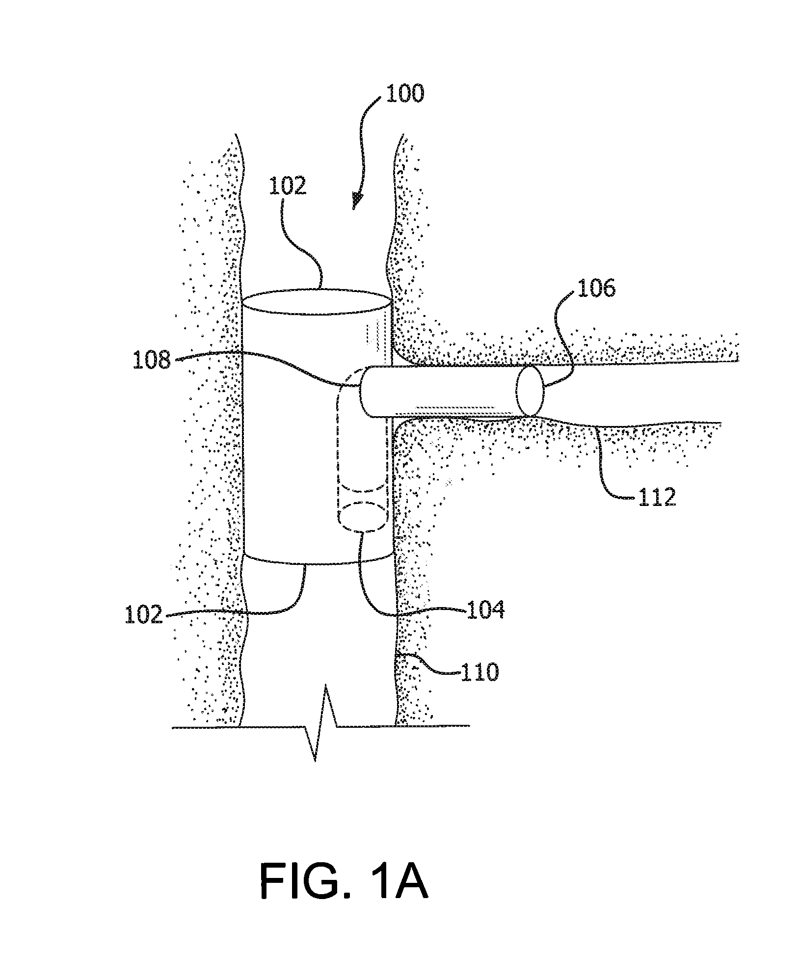
[0007]The one embodiment of the invention is directed to an improved, modular, bifurcated stent graft having an integral support tube. In another embod

Problems solved by technology

Aneurysms occur in blood vessels at sites where, due to age, disease or genetic predisposition of the patient, the strength or resilience of the vessel wall is insufficient to prevent ballooning or stretching of the wall as blood passes through.
If the aneurysm is left untreated, the blood vessel wall may expand and rupture, often r

Method used


Image

  • Bifurcated highly conformable medical device branch access
  • Bifurcated highly conformable medical device branch access
  • Bifurcated highly conformable medical device branch access

Examples


example 1

Construction of a Highly Conformable Stent Graft

[0081]A flexible stent graft was assembled having the general configuration as shown in FIG. 8.

[0082]The stent graft was fabricated by initially extruding and expanding a tube of polytetrafluoroethylene (PTFE) to form a base tube. The base tube had a length of about 60 mm, a wall thickness of about 0.06 mm and a diameter of about 26 mm. The base tube had a substantial fibril orientation in the longitudinal direction so that the tube was relatively strong in the longitudinal direction while being relatively weak in the radial direction. The base tube was radially stretched over a mandrel having a diameter of about 31 mm.

[0083]To provide resistance to fluid permeation and to enhance the radial strength of the base tube, a film of densified ePTFE was wrapped over the base tube. The film was a thin, strong fluoropolymer; a particularly preferred material for this application is a non-porous ePTFE provided with an adhesive coating of thermo...

example 2

Construction of a Highly Conformable Stent Graft Having an Integral Side Branch Portal

[0093]Referring to FIGS. 2A and 2B, a metallic mandrel 200 was fabricated having a slot 202 formed into one end of the mandrel. The slot 202 terminates onto a back wall 204. The mandrel had a diameter of about 31 mm and the slot was about 12.5 mm wide, by about 10 mm deep and about 13 cm long. As shown in FIG. 2B, an inner tube 206 was radially stretched onto the mandrel 200, covering a portion of the mandrel groove 202. The inner tube was an extruded and expanded tube of polytetrafluoroethylene (PTFE). The inner tube had a length of about 60 mm, a wall thickness of about 0.06 mm and a diameter of about 26 mm. The inner tube had a substantial fibril orientation in the longitudinal direction so that the tube was relatively strong in the longitudinal direction while being relatively weak in the radial direction.

[0094]As shown in FIG. 3A the mandrel 200 was covered by the inner tube 206. The inner tub...


PUM

PropertyMeasurementUnit
Angleaaaaaaaaaa
Flow rateaaaaaaaaaa
Shapeaaaaaaaaaa

Abstract

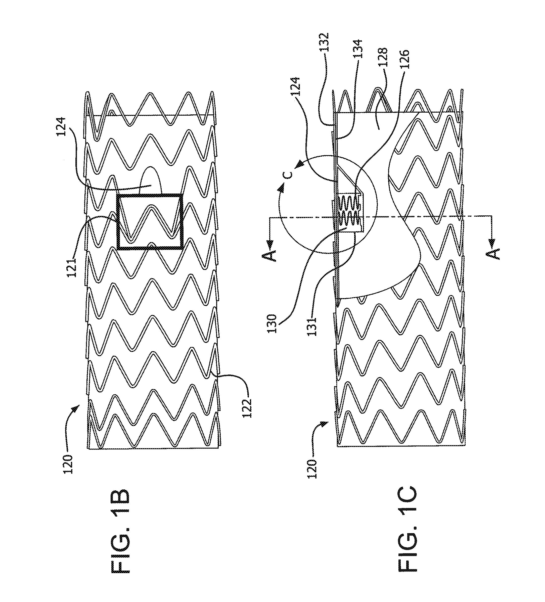
The present invention comprises a highly conformable stent graft with an optional portal for a side branch device. Said stent graft comprises a graft being supported by a stent, wherein said stent comprises undulations each which comprise apices in opposing first and second directions and a tape member attached to said stent and to said graft such that the tape member edge is aligned to the edge of the apices in the first direction of the each of the undulations, thus confining the apices in the first direction of the undulations to the graft and wherein the apices in the second direction of the undulation are not confined relative to the graft; wherein said graft forms unidirectional pleats where longitudinally compressed and wherein said apices in the first direction of said undulation is positioned under an adjacent pleat when compressed. The invention also discloses and claims methods of making and using said highly conformable stent graft and method of making the optional portal.

Description

CROSS-REFERENCE TO RELATED APPLICATIONS[0001]This application claims benefit to U.S. Provisional Patent Application Ser. No. 61 / 250,313 filed Oct. 9, 2009, which is incorporated by reference herein for all purposesFIELD OF THE INVENTION[0002]One aspect of the invention is directed to an improved, modular, bifurcated stent graft having an integral support tube. Another aspect of the invention is directed to a highly conformable stent graft with an optional bifurcation.BACKGROUND[0003]Aneurysms occur in blood vessels at sites where, due to age, disease or genetic predisposition of the patient, the strength or resilience of the vessel wall is insufficient to prevent ballooning or stretching of the wall as blood passes through. If the aneurysm is left untreated, the blood vessel wall may expand and rupture, often resulting in death.[0004]To prevent rupturing of an aneurysm, a stent graft may be introduced into a blood vessel percutaneously and deployed to span the aneurysmal sac. Stent ...

Claims


Application Information

Patent Timeline
IPC IPC(8): A61F2/06
CPCA61F2/07Y10T29/49885A61F2/88A61F2/954A61F2002/061A61F2002/067A61F2002/075A61F2240/001A61F2/852A61F2/89A61F2220/0025A61F2220/0033A61F2220/005A61F2230/001Y10T156/1056A61F2/856A61F2/06A61F2/86
Inventor DAUGHERTY, JOHN R.HAGAMAN, LOGAN R.KOVACH, LARRY J.
Owner WL GORE & ASSOC INC
Why Eureka
Try Eureka