Eureka AIR delivers breakthrough ideas for toughest innovation challenges, trusted by R&D personnel around the world.

Accelerator-pedal reaction force control apparatus

a technology of reaction force and control apparatus, which is applied in the direction of mechanical control devices, process and machine control, instruments, etc., can solve the problems of unfavorable operation behavior, unfavorable fuel consumption reduction, and the acceleration pedal will unstably move up and down against the intention of the driver, so as to reduce the acceleration reaction force and increase the reaction force of the accelerator

Active Publication Date: 2011-04-14
NISSAN MOTOR CO LTD
View PDF12 Cites 18 Cited by
  • Summary
  • Abstract
  • Description
  • Claims
  • Application Information

AI Technical Summary

Benefits of technology

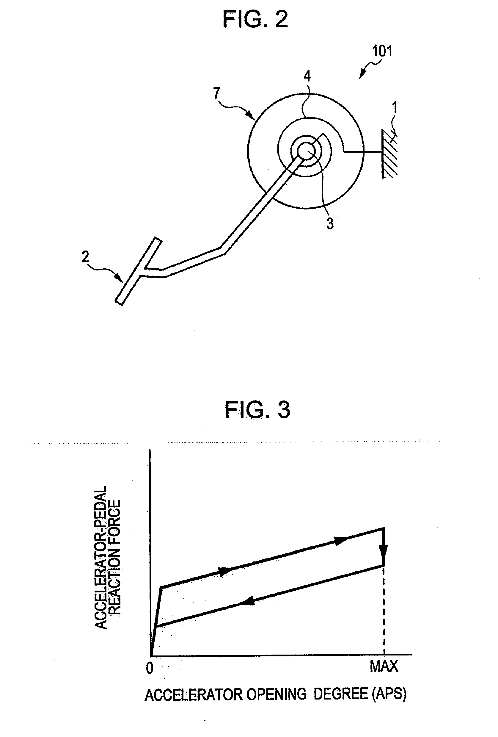
[0010]In one aspect, the present disclosure relates to an accelerator reaction force control apparatus for a vehicle including a means for detecting a position of an accelerator, a means for changing a reaction force of the accelerator, and a controller configured to control the reaction force changing means, wherein the controller sets a first position threshold of the accelerator associated with an operating state of the vehicle, the controller controls the reaction-force changing means to add an increase to the reaction force of the accelerator when the accelerator position exceeds the first position threshold, the controller sets an second position threshold of the accelerator smaller than the first position threshold, and the controller controls the reaction force changing means to eliminate the increase in the reaction force of the accelerator when the accelerator position is reduced to equal to or less than the second position threshold.
[0012]In another aspect, the present disclosure relates to a method to control a reaction force of an accelerator of a vehicle including detecting a position of the accelerator, setting a first position threshold of the accelerator based upon an operating state of the vehicle, setting an second position threshold of the accelerator below the first position threshold, increasing a reaction force of the accelerator when the accelerator position exceeds the first position threshold, and reducing the increased reaction force of the accelerator when the accelerator position is reduced from a position in excess of the first position threshold to a position equal to or less than the second position threshold.

Problems solved by technology

For this reason, this type of reaction-force control apparatus which contributes to the reduction in fuel consumption cannot be put into practical use unless the reduction in fuel consumption can be achieved together with satisfactory operational feel of the accelerator pedal and operability of the vehicle.
As a result of these tests, it was found that if the reaction force is increased or the increase therein is eliminated at a certain accelerator opening degree which corresponds to a boundary as described in Patent Document 1, unfavorable operational behavior finally occurs as a result of an unintentional response by a driver.
Thus, when the driver increases the accelerator opening degree such that the fuel efficiency of the vehicle changes beyond a certain boundary, there is a risk that the accelerator pedal will unstably move up and down against the intention of the driver.
This makes the user feel uncomfortable and degrades the operability of the vehicle.

Method used


Image

  • Accelerator-pedal reaction force control apparatus
  • Accelerator-pedal reaction force control apparatus
  • Accelerator-pedal reaction force control apparatus

Examples


Embodiment Construction

[0026]Embodiments of the present disclosure will be described in detail below with reference to the drawings.

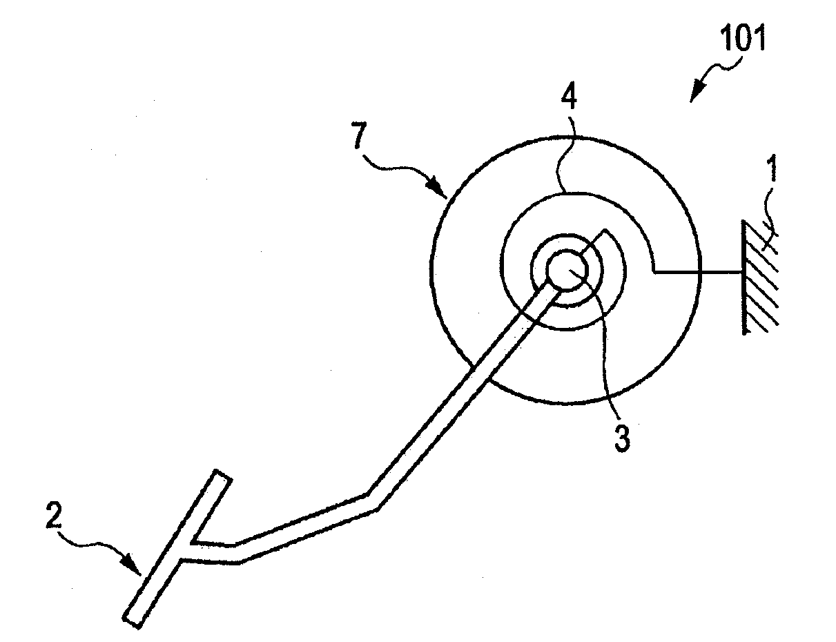
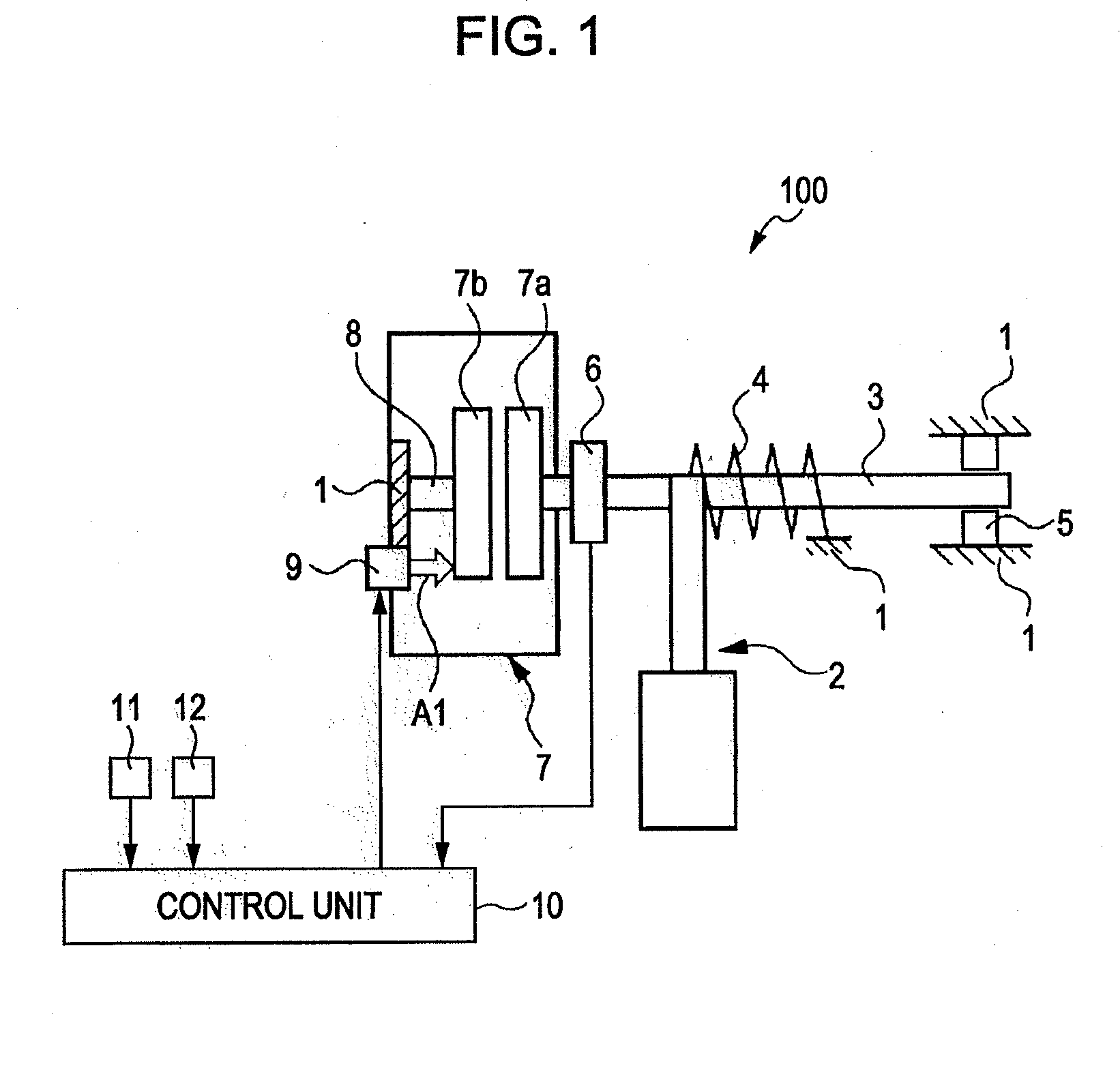
[0027]FIG. 1 is a schematic diagram illustrating the system structure of an accelerator-pedal reaction force control apparatus 100. The accelerator-pedal reaction force control apparatus 100 may control a reaction force (operational reaction force) of an accelerator pedal 2 provided in a vehicle body 1 of a vehicle (not shown). While the term “accelerator pedal” or “accelerator” is used throughout this specification, it should be understood that such terms should not be limited to any particular embodiment or style of input device. In particular, while a “pedal” inside the passenger compartment is described, it should be understood that the “accelerator” may be a device in the engine compartment responsive to electrical, hydraulic, or mechanical signals produced by a pedal (or other device) in the passenger compartment. Additionally, while the device in the passenger compartm...


PUM


Abstract

A utility vehicle comprising a cab which houses a steering wheel assembly is provided wherein a steering wheel (22) is rotatably mounted to a support body (24). The support body, or steering console, is mounted on an armrest assembly (40) or control console positioned to one side of a driver's seat (18). By providing an asymmetric mounting arrangement for the steering console, the space underneath is left clear of any supporting structure thus providing improved legroom for the driver.

Description

CROSS-REFERENCE TO RELATED APPLICATIONS[0001]The present application claims priority from Japanese Patent Application No. 2008-197386, filed Jul. 31, 2008 and Japanese Patent Application No. 2009-123001, filed May 21, 2009, the contents of which are both hereby incorporated by reference in their entirety.BACKGROUND OF THE DISCLOSURE[0002]1. Field of the Disclosure[0003]The present disclosure relates to an accelerator-pedal reaction force control apparatus which controls a reaction force of an accelerator pedal of a vehicle.[0004]2. Description of the Related Art[0005]Japanese Unexamined Patent Application Publication No. 2003-120339 (hereinafter referred to as Patent Document 1) discloses a technique for increasing a reaction force against depression (hereinafter also referred to simply as reaction force) of an accelerator pedal. This technique is applied to an engine which switches between a first operation method (for example, homogeneous combustion) for a high-rotational-speed, h...

Claims


Application Information

Patent Timeline
Patent Type & Authority Applications(United States)
IPC IPC(8): G05G5/03G06F19/00
CPCB60K26/021F02D11/02Y10T477/692G05G5/03G05G1/30B60K26/04
Inventor SHIOMI, MASAOSAKAGUCHI, SHIGEYUKI
Owner NISSAN MOTOR CO LTD
Why Eureka
Eureka Blog
Learn More