Peripheral device and device connection system

a technology of peripheral devices and connection systems, applied in data switching networks, frequency-division multiplexes, instruments, etc., can solve the problems of external storage units not being connected with electronic devices, external storage units not being able to directly communicate with electronic devices, communication protocols not being able to connect with electronic devices, etc., to achieve data access from a device subject

Inactive Publication Date: 2011-04-14
SONY CORP
View PDF5 Cites 34 Cited by
  • Summary
  • Abstract
  • Description
  • Claims
  • Application Information

AI Technical Summary

Benefits of technology

[0025]As described above and according to embodiments of the present invention, the data access from a device subject to connection (or a connection mate device), such as an electronic device, to a device subject to communication (or a communication mate device) can be universally facilitated.

Problems solved by technology

Some of the externally attached storage units cannot connect to electronic devices or directly communicate with electronic devices.
For example, the external storage units that were manufactured before the establishment of new communication protocols are not connectable with the electronic devices configured to operate in accordance with the newly established communication protocols.

Method used


Image

  • Peripheral device and device connection system
  • Peripheral device and device connection system
  • Peripheral device and device connection system

Examples


first embodiment

(1) The First Embodiment

Configuration of a Device Connection System 1

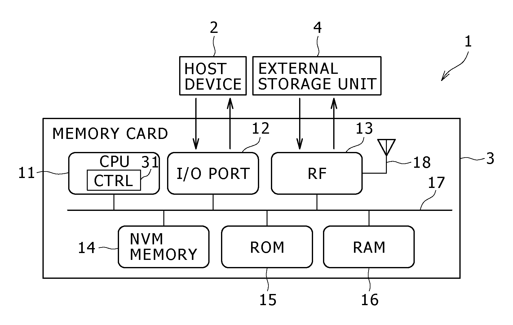
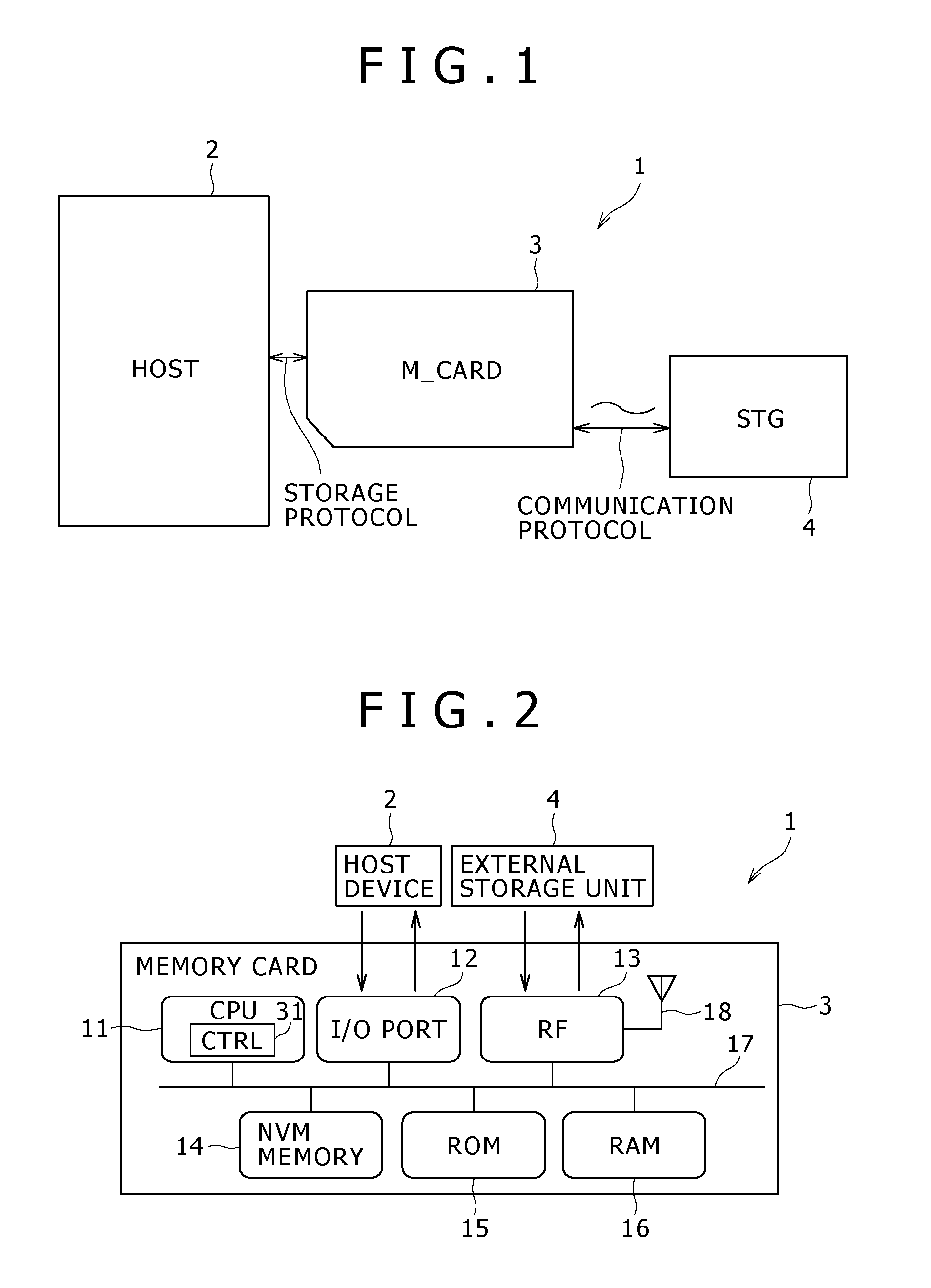
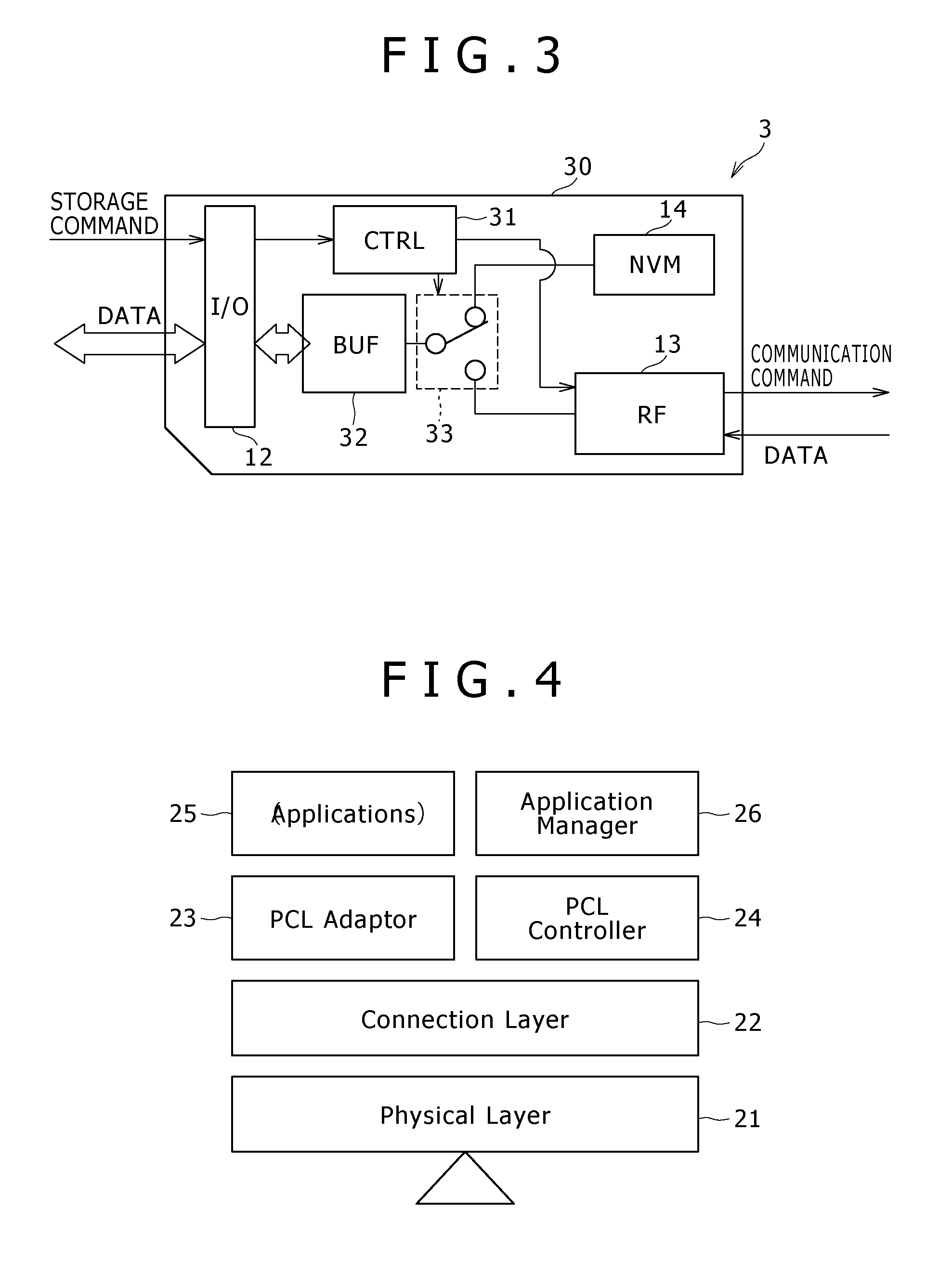
[0053]Now, referring to FIG. 1, there is shown a system configuration diagram illustrating the device connection system 1 practiced as the first embodiment of the invention. The device connection system 1 shown in FIG. 1 has a host device 2, a memory card 3, and an external storage unit 4.

[0054]The memory card 3 has a card-shaped housing 30. The memory card 3 is a storage unit with the housing 30 detachably inserted in the host device 2.

[0055]The memory card 3 thus configured includes a card-type semiconductor memory based on a nonvolatile memory, such as a flash memory for example.

[0056]The memory card 3 connected to the host device 2 stores data supplied from the host device 2 on the basis of a memory card IF storage protocol.

[0057]In addition, the memory card 3 outputs requested data to the host device 2 in accordance with the storage protocol.

[0058]Further, the memory card 3 executes wireless communication with...

second embodiment

(2) The Second Embodiment

Configuration of a Device Connection System 1

[0233]Referring to FIG. 16, there is shown a schematic block diagram illustrating a memory card 3 practiced as a second embodiment of the invention.

[0234]The memory card 3 shown in FIG. 16 has a detection terminal 41, a power supply terminal 42, and a power supply circuit 43.

[0235]The memory card 3 shown in FIG. 16 searches the external storage unit 4 after the detection of the memory card 3 by the host device 2. Depending on a search result, the host device 2 can access either the nonvolatile memory (NVM) 14 or the external storage unit 4.

[0236]The configurations of the memory card 3 and the device connection system 1 are substantially the same those of the embodiment 1 except for those described above. Therefore, similar components are denoted by the same reference numerals and the description thereof will be skipped.

[0237]The detection terminal 41 is connected to the ground of the memory card 3.

[0238]Then, when...

third embodiment

(3) The Third Embodiment

Configuration of a Device Connection System 1

[0263]Referring to FIG. 17, there is shown a schematic block diagram illustrating a memory card 3 practiced as a third embodiment of the invention.

[0264]The memory card 3 shown in FIG. 17 has a transistor 51 and a battery 52.

[0265]In addition, unlike the second embodiment described above, the memory card 3 shown in FIG. 17 has neither the nonvolatile memory (NVM) 14 nor the selector switch 33. A wireless communication block 13 is connected to a buffer memory 32.

[0266]With the memory card 3 shown in FIG. 17, the power supplied from the battery 52 or a host device 2 drive the wireless communication block 13 to search for an external storage unit 4 always or intermittently.

[0267]A control block 31 controls the transistor 51 in accordance with a result of the search made by the wireless communication block 13, thereby making the host device 2 detect the memory card 3.

[0268]The configurations of the memory card 3 and th...


PUM


Abstract

A peripheral device includes: an input/output block connected to a device subject to connection; a communication block configured to communicate with a device subject to communication; and a conversion block configured, if the device subject to communication is a storage device, to convert a storage access command output by the device subject to connection to the input/output block into a communication command that is transferred between the communication block and the device subject to communication, wherein the communication block transmits the communication command generated by the conversion block to the device subject to communication and transfers, with the device subject to communication, one of data that is written by the device subject to connection to the device subject to communication and data that is read from the device subject to communication.

Description

BACKGROUND OF THE INVENTION[0001]1. Field of the Invention[0002]The present invention relates to a peripheral device and a device connection system that are configured, connected to a device subject to connection (or a connection mate device), to execute communication with another device subject to connection.[0003]2. Description of the Related Art[0004]Referring to Japanese Patent Laid-open No. 2008-164120, there is disclosed a memory card that is detachably connected to electronic devices.SUMMARY OF THE INVENTION[0005]The above-mentioned another device that an electronic device wants to access for getting data, for example, includes external storage units.[0006]These external storage units are externally attached hard disk drives, for example. Some of the externally attached storage units cannot connect to electronic devices or directly communicate with electronic devices.[0007]For example, the external storage units that were manufactured before the establishment of new communica...

Claims


Application Information

Patent Timeline
Patent Type & Authority Applications(United States)
IPC IPC(8): G06F3/00G06F1/26
CPCG06F1/26G06F3/0679G06F3/0661G06F3/0607
Inventor OKAUE, TAKUMIKUNO, HIROSHITASHIRO, JUNOKUBO, HIDEAKIISHIMOTO, TAKESHI
Owner SONY CORP
Why Eureka
Try Eureka