Method for Selecting Shapes in a Graphical Display

a graphical display and shape technology, applied in the field of process plants, can solve the problems of limited graphical capabilities of these displays, difficult, if not impossible, to use a graphical program created to support a control or other operator in maintenance, configuration or simulation functions, and limited in usefulness to the specific process functions

Active Publication Date: 2011-04-14
FISHER-ROSEMOUNT SYST INC
View PDF3 Cites 29 Cited by
  • Summary
  • Abstract
  • Description
  • Claims
  • Application Information

AI Technical Summary

Benefits of technology

[0013]In some embodiments, a computing device may reduce a number of composite shape sub-elements stored in a runtime memory of a graphical display for the process control system. The device may comprise a processor, a memory, a display, and a composite shape sub-element selection application. The application may be maintained in the memory and executed on the processor to select a composite shape sub-element for display within a composite shape of the graphical display. The composite shape may be configured to include a selector shape, a plurality of composite shape sub-elements, and an expression. The composite shape sub-element selection application may also include instructions for evaluating the expression at runtime to determine an expression result and identifying a composite shape sub-element using the expression result. The composite shape sub-element may be identified from the plurality of composite shape sub-elements. The application may then display the identified composite shape sub- element within or in place of the selector shape and

Problems solved by technology

However, these graphical display applications have, in the past, been created as part of or to support the specific applications with which they are associated, and thus are generally limited in usefulness to the specific process function for which they were created.
For example, it is difficult, if not impossible, to use a graphical program created to support a control or other operator in a maintenance, a configuration or a simulation function.
Still further, the limited graphical capabilities of these displays are hard to implement and are not done so as part of any graphical object.
This process is tedious, time consuming and may be fraught with error.
This method of “stacking” the unique, child

Method used


Image

  • Method for Selecting Shapes in a Graphical Display
  • Method for Selecting Shapes in a Graphical Display
  • Method for Selecting Shapes in a Graphical Display

Examples


Embodiment Construction

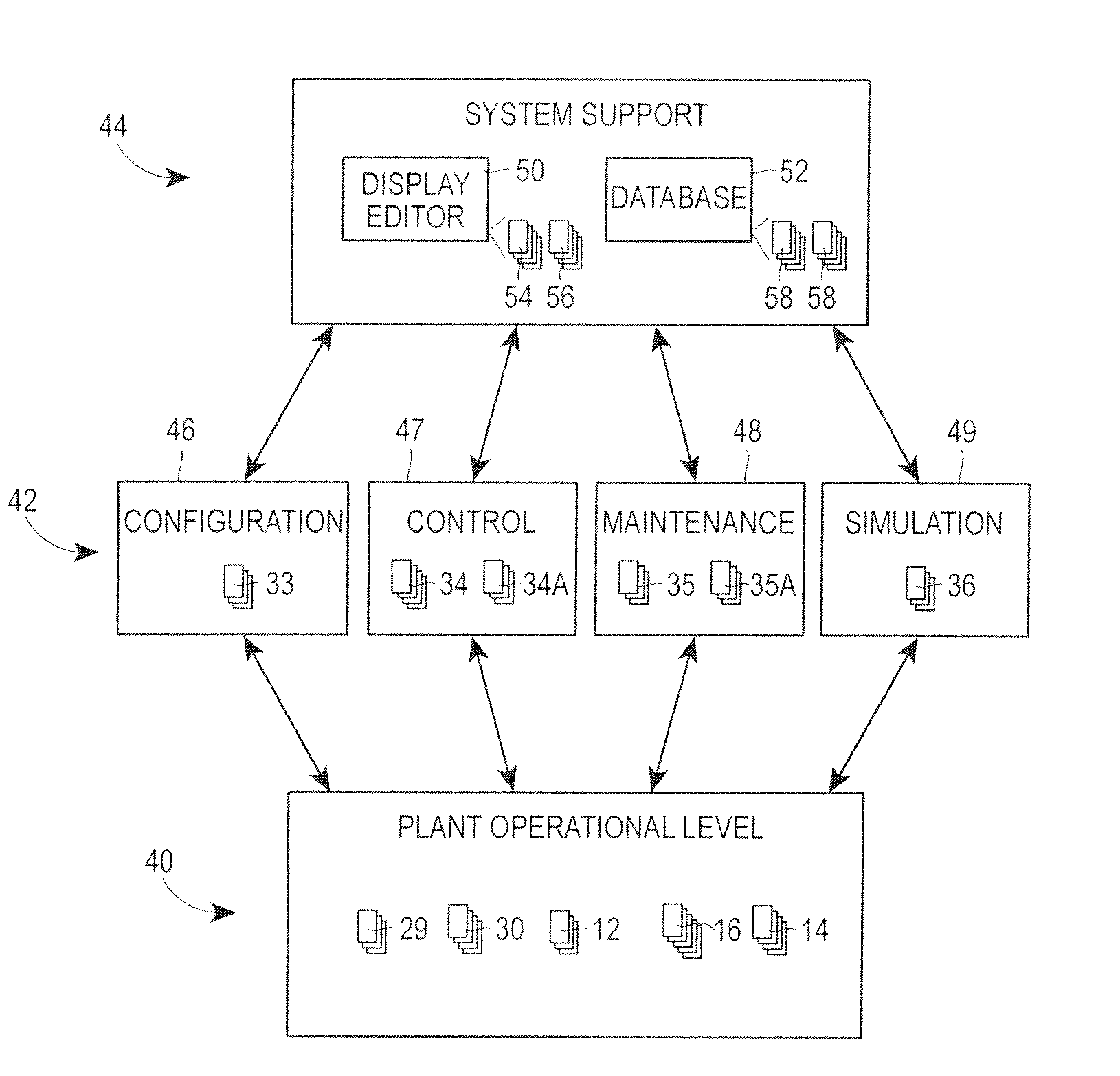
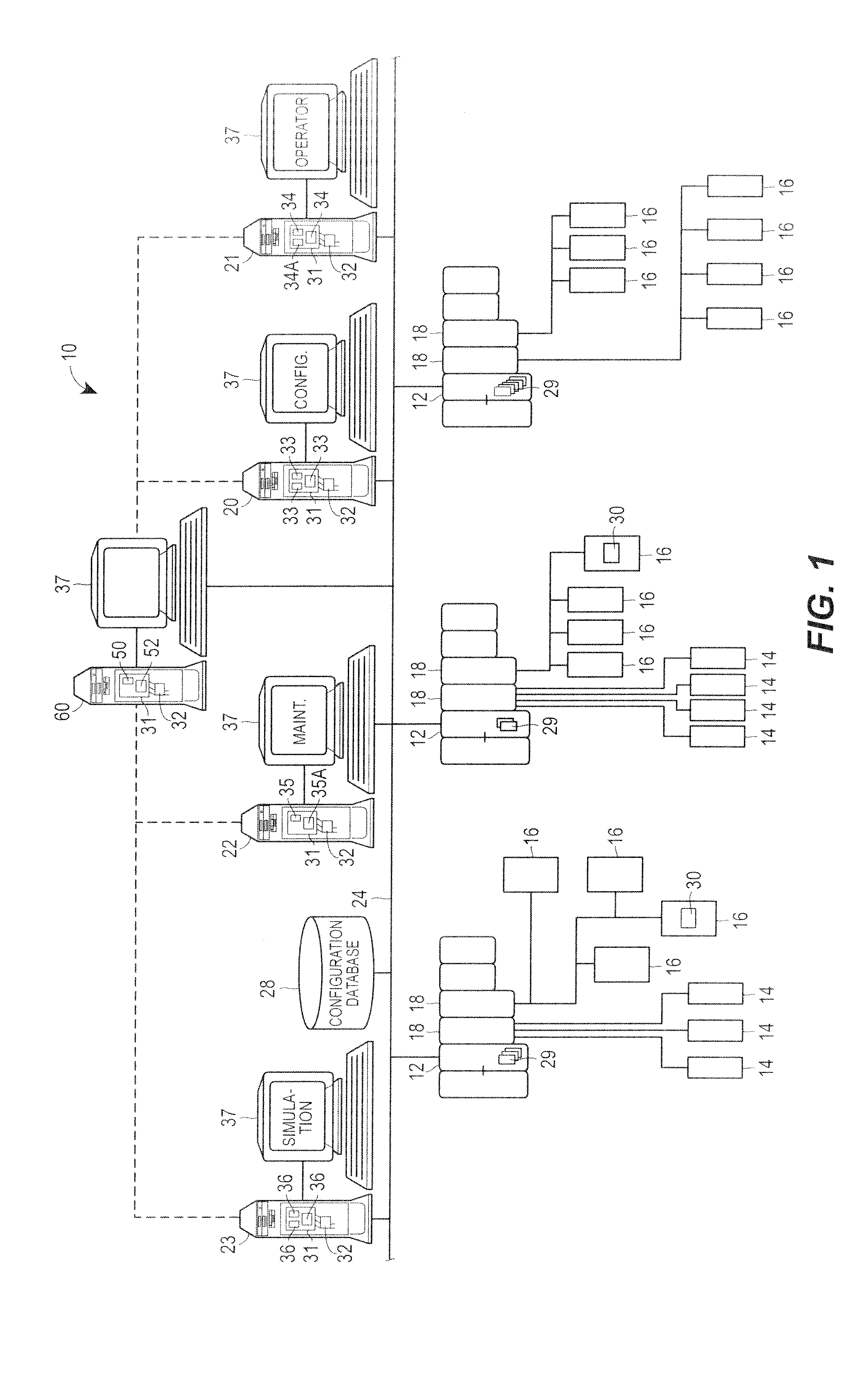
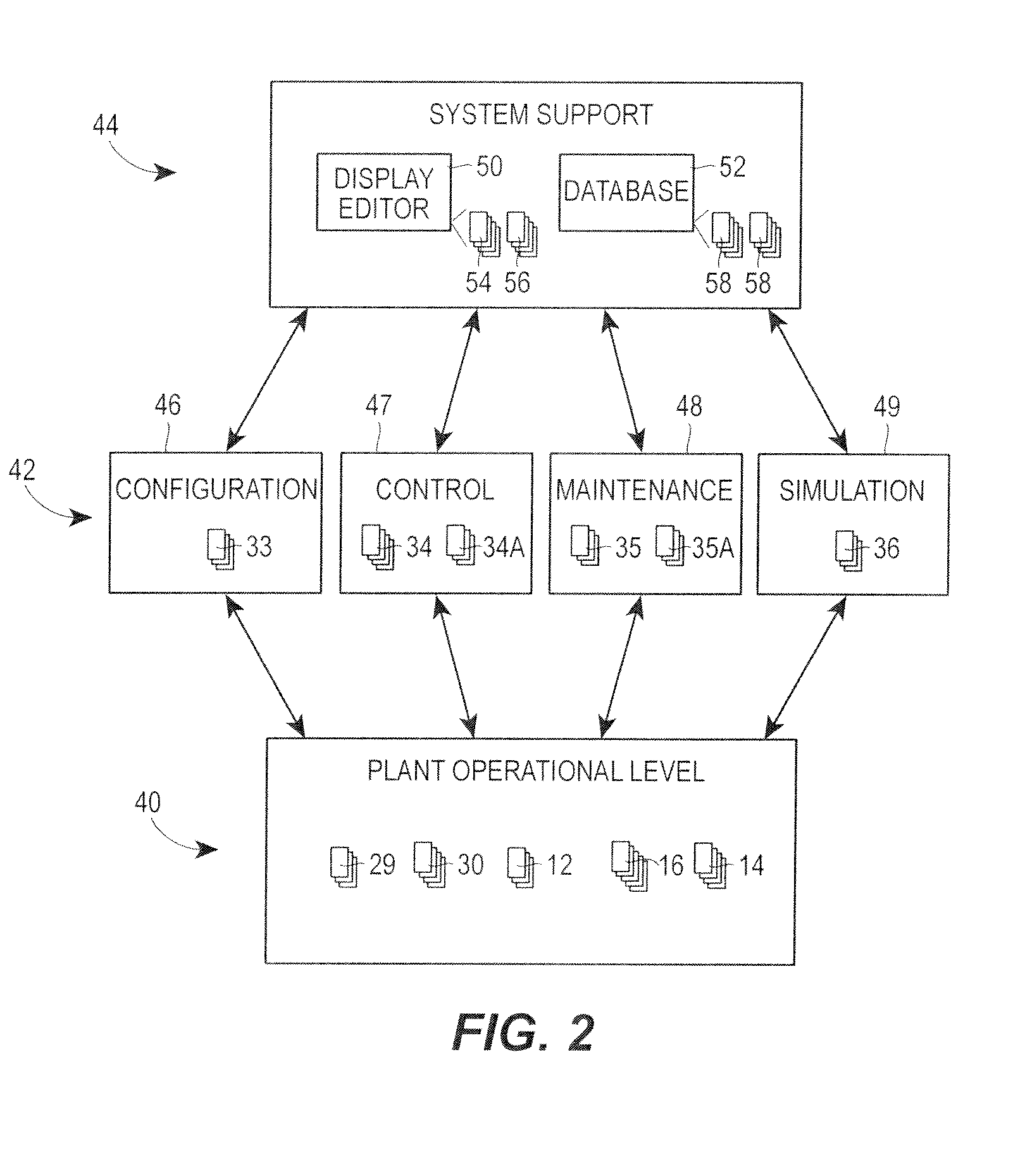
[0026]FIG. 1 illustrates an example process plant 10 in which system level graphical support is provided to various functional areas of the plant 10. As is typical, the process plant 10 includes a distributed process control system having one or more controllers 12, each connected to one or more field devices 14 and 16 via input / output (I / O) devices or cards 18 which may be, for example, Fieldbus interfaces, Profibus interfaces, HART interfaces, standard 4-20 ma interfaces, etc. The controllers 12 are also coupled to one or more host or operator workstations 20-23 via a data highway 24 which may be, for example, an Ethernet link. A database 28 may be connected to the data highway 24 and operates as a data historian to collect and store parameter, status and other data associated with the controllers and field devices within the plant 10 and / or as a configuration database that stores the current configuration of the process control system within the plant 10 as downloaded to and stor...


PUM


Abstract

A selector shape may serve as the background to a configurable composite shape and may include one or more expressions that are evaluated to select between several composite shape definitions via links to the definition. Each selector shape includes an animation expression and a lookup table converter to select an identifier of the composite definition to be loaded and displayed. When the value of the animation expression changes, the value may be matched to the name of a new composite definition using the lookup table, and the new definition may be displayed. The previously-used composite definition may then be marked for removal by a caching system, and removed. These selector shapes also enable the same graphic element to be used in displays designed for different types of display devices, such as display devices having large display screens, standard computer screens and very small display screens.

Description

TECHNICAL FIELD[0001]The present invention relates generally to process plants and, more particularly, to the integration and use of a graphic display editor and graphic display objects of a process control and simulation system to enable the creation of a selector shape that selects between linked composite shapes at runtime to display different information within the selector shape.DESCRIPTION OF THE RELATED ART[0002]Distributed process control systems, like those used in chemical, petroleum or other processes, typically include one or more process controllers communicatively coupled to one or more field devices via analog, digital or combined analog and digital buses. The field devices, which may be, for example, valves, valve positioners, switches and transmitters (e.g., temperature, pressure, level and flow rate sensors), are located within the process environment and perform process functions such as opening or closing valves, measuring process parameters, etc. Smart field dev...

Claims


Application Information

Patent Timeline
IPC IPC(8): G06F3/048
CPCG05B19/0426G06F15/0225G05B2219/32128G05B2219/23258G05B19/41845G06T1/60G06T11/20G06T11/40
Inventor CAMPNEY, BRUCE H.HAMMACK, STEPHEN G.BEOUGHTER, KEN J.
Owner FISHER-ROSEMOUNT SYST INC
Why Eureka
Try Eureka