Valve train device

a technology of valve train and valve body, which is applied in the direction of non-mechanical valves, electrical control, magnetic bodies, etc., can solve the problems of low error-proneness and achieve the effect of reducing the vulnerability to faults

Active Publication Date: 2011-04-21
DAIMLER AG
View PDF2 Cites 9 Cited by
  • Summary
  • Abstract
  • Description
  • Claims
  • Application Information

AI Technical Summary

Benefits of technology

to reduce a vulnerability to faults in the process of monitoring the shifting operation.

Problems solved by technology

In particular, the monitoring by evaluation of the characteristic value for the voltage integral may depend only on an initial state and a final state and is independent of its progress between the initial state and the final state, resulting in a particular low error-proneness, for example with respect to pulse spikes.

Method used


Image

  • Valve train device
  • Valve train device
  • Valve train device

Examples


Embodiment Construction

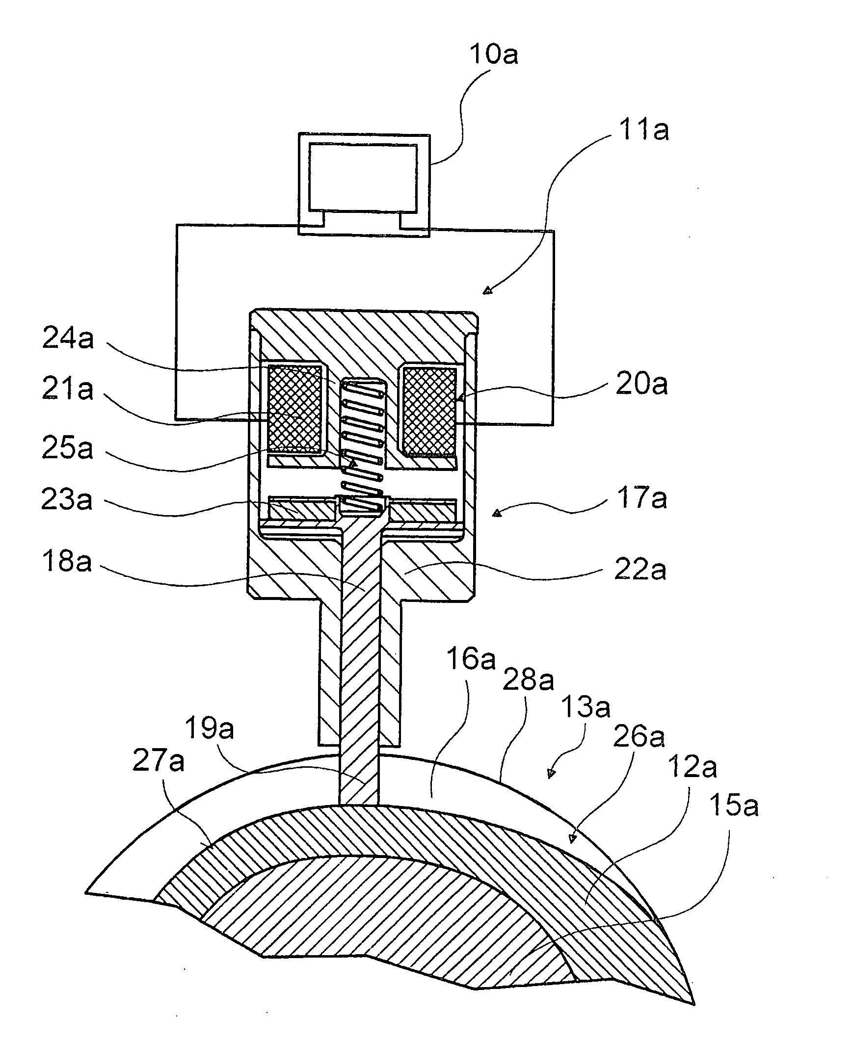
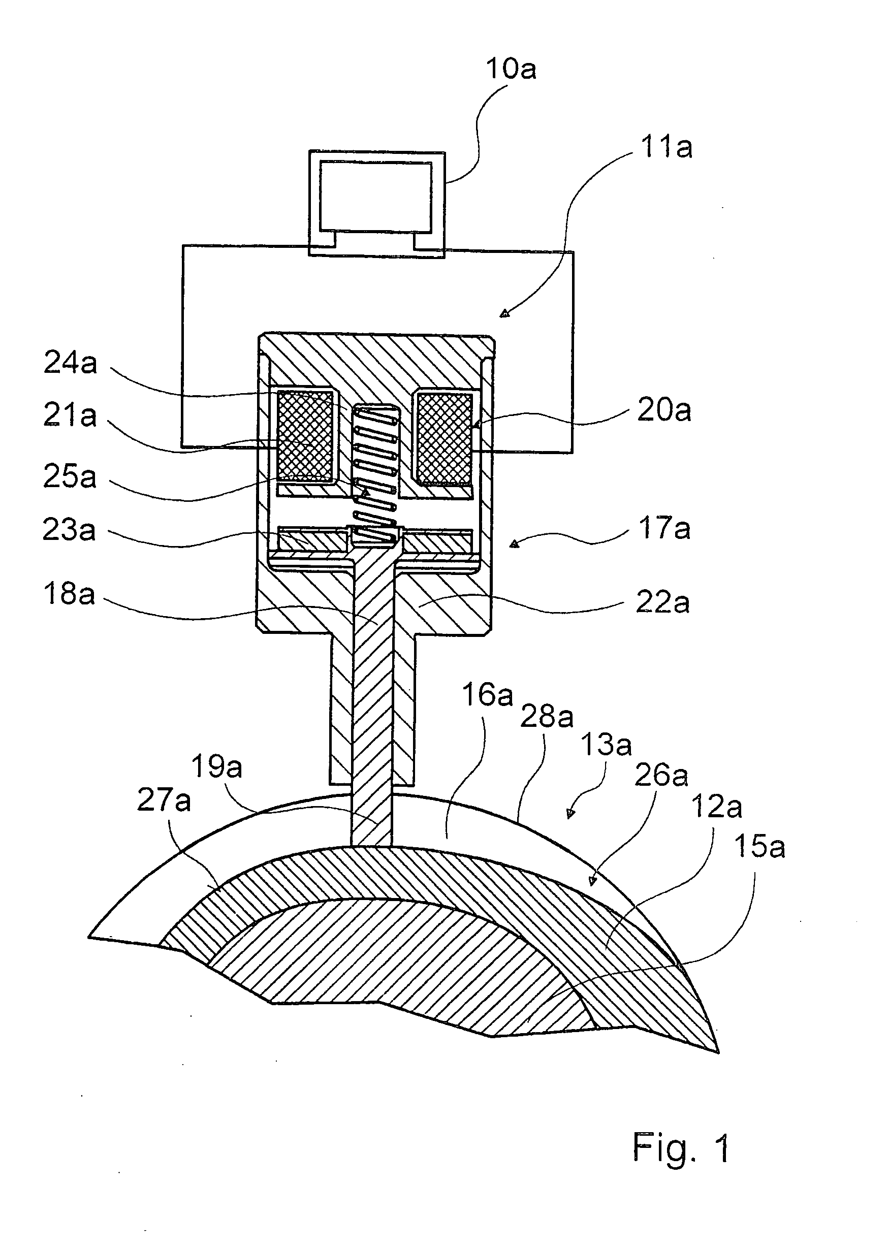
FIG. 1 shows a control device for a valve train of an internal combustion engine. The valve train control device comprises a cam element 12a located non-rotatably but axially movably with respect to a camshaft 15a. The cam element 12a is displaced by means of a switching unit 11a and a shift gate 13a. The shift gate 13a has a gate track 16a in the form of a groove.

The switching unit 11a comprises an actuator 17a and a switching element 18a. The switching element 18a is in the form of a switching pin 19a which is extended in a switching position of the switching element 18a. In the switching position, the switching pin 19a engages the gate track 16a of the shift gate 13a.

The actuator 17a which moves the switching element 18a, comprises a solenoid unit 20a. The solenoid unit 20a comprises a coil 21a located in a stator 22a of the solenoid unit. The coil 21a can generate a magnetic field which interacts with a permanent magnet 23a located in the switching element 18a. In this way, the...


PUM


Abstract

In a valve drive train device, in particular for a valve drive of an internal combustion engine, with a switching unit comprising an actuator with a solenoid unit and with a control unit for monitoring switching operations of the switching unit provided for switching an axially displaceable cam element by means of a switch gate, the control unit for monitoring the switching unit is taking into account at least one characteristic value of a voltage integral over a voltage which is induced in a coil of the switching unit during the switching operation and is adjusting the value with respect to a characteristic limit value stored in the control unit.

Description

BACKGROUND OF THE INVENTIONThe invention relates to a valve train device for an internal combustion engine including a control unit for monitoring the operation of a shifting unit for axially shifting a cam element by means of a shift gate.From DE 10 2004 030 779 A1, a valve train device, in particular for an internal combustion engine, is known, which comprises a control unit provided for monitoring a switching operation of a switching unit designed for switching an axially displaceable cam element by means of a shift gate.It is the principal object of the invention to reduce a vulnerability to faults in the process of monitoring the shifting operation.SUMMARY OF THE INVENTIONIn a valve drive train device, in particular for a valve drive of an internal combustion engine, with a switching unit comprising an actuator with a solenoid unit and with a control unit for monitoring switching operations of the switching unit provided for switching an axially displaceable cam element by mean...

Claims


Application Information

Patent Timeline
Patent Type & Authority Applications(United States)
IPC IPC(8): F01L9/04H02K41/035
CPCF01L2013/0052F01L13/0036F01L2013/101F01L2201/00F01L2800/11F01L2820/01F02D41/20F02D41/221F02D2041/001F02D2041/2051H01F7/1844Y02T10/40
Inventor GREGOR, MATTHIASJAKOBI, RICHARD
Owner DAIMLER AG
Why Eureka
Try Eureka