Method of detection of welding workpiece position using movable electrode

a technology of welding workpiece position and movable electrode, which is applied in the direction of instruments, soldering devices, auxillary welding devices, etc., can solve the problems of inability to accurately detect contact, inability to detect the surface position of the welding workpiece at the movable electrode side and the surface position at the strike position also becoming uncertain, and the current or torque of the servo motor ending up exceeding a threshold value. , to achieve the effect of simplifying the work procedure for workers

Active Publication Date: 2011-04-21
FANUC LTD
View PDF3 Cites 23 Cited by
  • Summary
  • Abstract
  • Description
  • Claims
  • Application Information

AI Technical Summary

Benefits of technology

[0054]Furthermore, in the above method of detection of the welding workpiece position, it is possible to execute welding program instructions so as to detect the welding workpiece position by the movable electrode. It is possible to perform

Problems solved by technology

If such a judgment of contact of the movable electrode and counter electrode with the welding workpiece is performed visually by a worker, depending on the degree of skill of the worker and the viewing conditions in the work environment, contact may not be able to be accurately detected and therefore detection of the surface position of the welding workpiece at the movable electrode side and surface position at the counter electrode side at the strike position also becomes uncertain.
As a result, due to the variation of the current or torque of the servo motor caused by the dynamic friction of the drive mechanism of the movable electrode, the current or torque of the servo motor ends up exceeding a threshold value for judging contact and erroneous detection of contact of the movable electrode and welding workpiece occurs in some cases.
However, if the threshold value is large, the movable electrode is moved from when actually contacting the welding workpiece to when it is judged to have contacted the welding workpiece, so the amount of elastic deformation of the welding workpiece becomes larger and the surface position of the welding workpiece is no longer able to be accurately detected.
Further, in the worst case, the welding workpiece is liable to end up being caused to plastically deform.
Therefore, it is not possible to strictly calculate the amount of elastic deformation of the welding workpiece.
Therefore, in the case of a soft welding workpiece, the change of the current or torque of the servo motor when the movable electrode and welding workpiece contact is hidden by the variation of the current or torque of the servo motor due to the dynamic friction, so detection of the contact of the movable electrode and welding workpiece becomes difficult and the precision of detection of contact deteriorates.
However, if slowing the speed of movement of the movable electrode, the problem arises that the time required for detection of the surface position of the welding workpiece by the movable electrode becomes longer and therefore the operation becomes impractical.
However, setting the thickness of the welding workpiece takes time, so there is the problem that it is difficult to set the thicknesses at each o

Method used


Image

  • Method of detection of welding workpiece position using movable electrode
  • Method of detection of welding workpiece position using movable electrode
  • Method of detection of welding workpiece position using movable electrode

Examples


embodiment a1

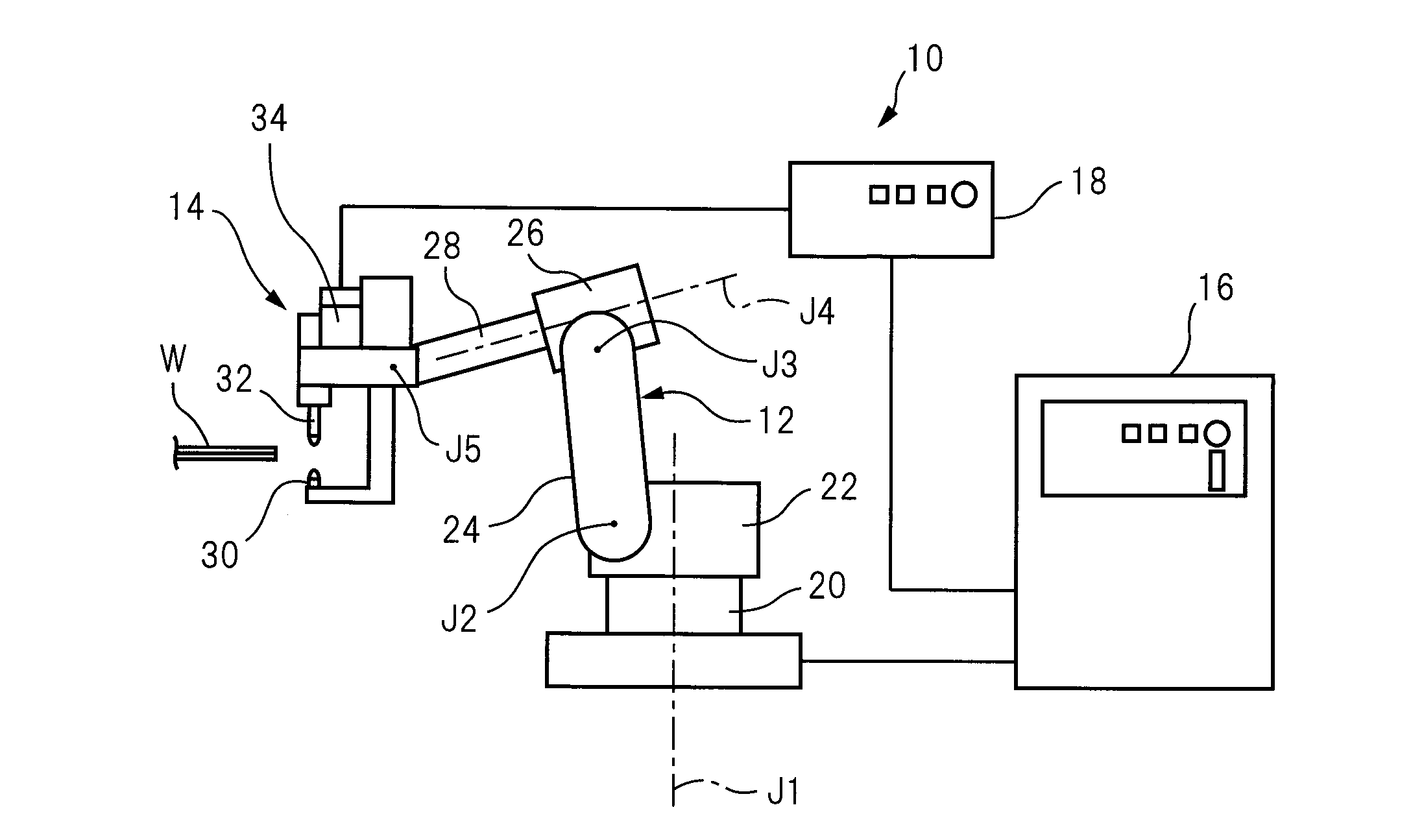
[0122]Referring to FIG. 6, an A1-th embodiment of a method of detection of the welding workpiece position of the present invention will be explained. In the A1-th embodiment, in the spot welding system 10 shown in FIG. 1, the speed Vg by which the servo motor 34 drives the movable electrode 30 is made “0” and the movable electrode 30 is made stationary with respect to the counter electrode 32. In that state, the multiarticulated robot 12 is used to hold the spot welding gun 14 and make it move relative to the welding workpiece W fixed to the workpiece table (not shown) by a speed Vr. Further, the servo motor 34 for driving the movable electrode 30 is set with a torque limit, so the torque will never increase over a certain value. To suppress deformation of the welding workpiece W due to pressing by the movable electrode 30, the torque limit is preferably set to as low a value as possible.

[0123]In this embodiment, first, the welding workpiece W is made to move between the movable ele...

embodiment a2

[0137]In the A2-th embodiment, in the spot welding system 10 shown in FIG. 1, the speed Vg by which the servo motor 34 drives the movable electrode 30 is not 0, the servo motor 34 is used to make the movable electrode 30 move, and, while doing so, the multiarticulated robot 12 is used to hold the spot welding gun 14 and make it move relative to a welding workpiece W fixed to the workpiece table (not shown) at a speed Vr. In this point, this differs from the A1-th embodiment. The rest of the points are similar to the A1-th embodiment. Therefore, here, the different parts will basically be explained and explanations of similar parts will be omitted.

[0138]In the A1-th embodiment, the speed Vg by which the servo motor 34 drives the movable electrode 30 is made “0” and the movable electrode 30 is made stationary with respect to the counter electrode 32, so there are the advantages that almost no variation of the current or torque of the servo motor 34 due to the dynamic friction of the m...

embodiment a3

[0157]Referring to FIG. 11, an A3-th embodiment of a method of detection of the welding workpiece position of the present invention will be explained. In the A3-th embodiment, in the spot welding system 10 shown in FIG. 1, the speed Vg by which the servo motor 34 drives the movable electrode is made “0” to make the movable electrode 30 stationary with respect to counter electrode 32 and, in that state, the multiarticulated robot 12 is used to hold the spot welding gun 14 and make it move relative to the welding workpiece W fixed to the workpiece table (not shown) at a speed Vr. Further, the servo motor 34 for driving the movable electrode 30 is set with a torque limit. The torque will therefore not increase above a constant value. To suppress deformation of the welding workpiece W due to pressing by the movable electrode 30, the torque limit is preferably set to as low a value as possible.

[0158]In this embodiment, first, the welding workpiece W is made to move between the movable el...


PUM

PropertyMeasurementUnit
Thicknessaaaaaaaaaa
Speedaaaaaaaaaa
Torqueaaaaaaaaaa

Abstract

A spot welding system including spot welding gun having a movable electrode driven by a servo motor, a counter electrode arranged facing it and with a multiarticulated robot, holding one of the welding workpiece and spot welding gun which moves welding workpiece and spot welding gun relative to each other and thereby make the movable electrode and the welding workpiece approach each other from a separated state or vice-versa, monitoring the current or torque of the servo motor, and detecting the surface position of the welding workpiece from the position of the movable electrode and the position of the multiarticulated robot when the trend of the current or torque changes. The precision of detection of the surface position of the welding workpiece by a movable electrode in a spot welding system can now be improved without lengthening the time required for detection of the surface position of the welding workpiece.

Description

BACKGROUND OF THE INVENTION[0001]1. Field of the Invention[0002]The present invention relates to a method of detection of a welding workpiece position which uses the movable electrode to detect a surface position of a welding workpiece in a spot welding system which uses a multiarticulated robot to make the welding workpiece and a spot welding gun move relative to each other, clamps the welding workpiece between a facing movable electrode and counter electrode of the spot welding gun, and spot welds the welding workpiece.[0003]2. Description of the Related Art[0004]A spot welding system is provided with a spot welding gun having a movable electrode driven by a servo motor and a counter electrode arranged facing the movable electrode and with a multiarticulated robot holding the spot welding gun at its front end. It uses the multiarticulated robot to make the welding workpiece and spot welding gun move relative to each other, then closes the movable electrode and counter electrode of...

Claims


Application Information

Patent Timeline
IPC IPC(8): B23K11/11
CPCB23K11/115
Inventor TAKAHASHI, HIROMITSUAOKI, TOSHIMICHINISHIMURA, AKINORI
Owner FANUC LTD
Why Eureka
Try Eureka