Aircraft landing gear arrangement and a nose landing gear assembly

a technology for landing gear and assembly, which is applied in the direction of wheel arrangement, aircraft braking arrangement, energy-saving operation measures, etc., can solve the problems of reducing the life of landing gear, limiting the use of ground movement, and limiting the use of towing

Inactive Publication Date: 2011-04-21
AIRBUS OPERATIONS LTD
View PDF5 Cites 24 Cited by
  • Summary
  • Abstract
  • Description
  • Claims
  • Application Information

AI Technical Summary

Benefits of technology

[0014]The motor preferably provides a braking function for use during taxiing. Also, the motor may include means to store energy from braking on landing and to allow re-use of that energy during taxiing. For example, the motor may be an electric motor which may be engaged during...

Problems solved by technology

While conventional towing offers some of these advantages its use as a means for ground movement, particularly for commercial aircraft, is often limited due to the structural impact upon the landing gear of the aircraft (typically the nose landing gear).
For example, older aircraft may not have been designed for extended towing operation as this would impose a significant weight penalty (due to the need to increase the weight of the landing gear structure to accommodate extra loads) and, therefore, the use of towing must be limited in order to avoid a reduction in the life of the landing gear.
As such the use of towing to move an aircraft is ...

Method used


Image

  • Aircraft landing gear arrangement and a nose landing gear assembly
  • Aircraft landing gear arrangement and a nose landing gear assembly
  • Aircraft landing gear arrangement and a nose landing gear assembly

Examples


Embodiment Construction

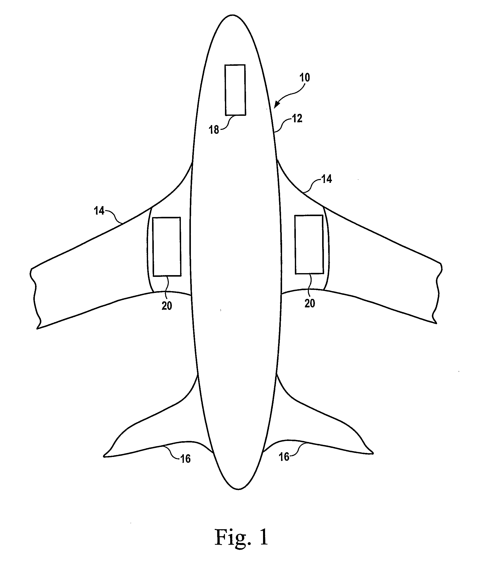
[0022]In FIG. 1, an aircraft 10 comprises a fuselage 12, wings 14 and a tail plane 16. A nose landing gear assembly 18 is arranged within a nose box of the fuselage 12 and two main landing gear assemblies are arranged at around the mid point of the fuselage either in the fuselage itself or, as shown in FIG. 1, in reinforced nacelles at the roots of the wings 14.

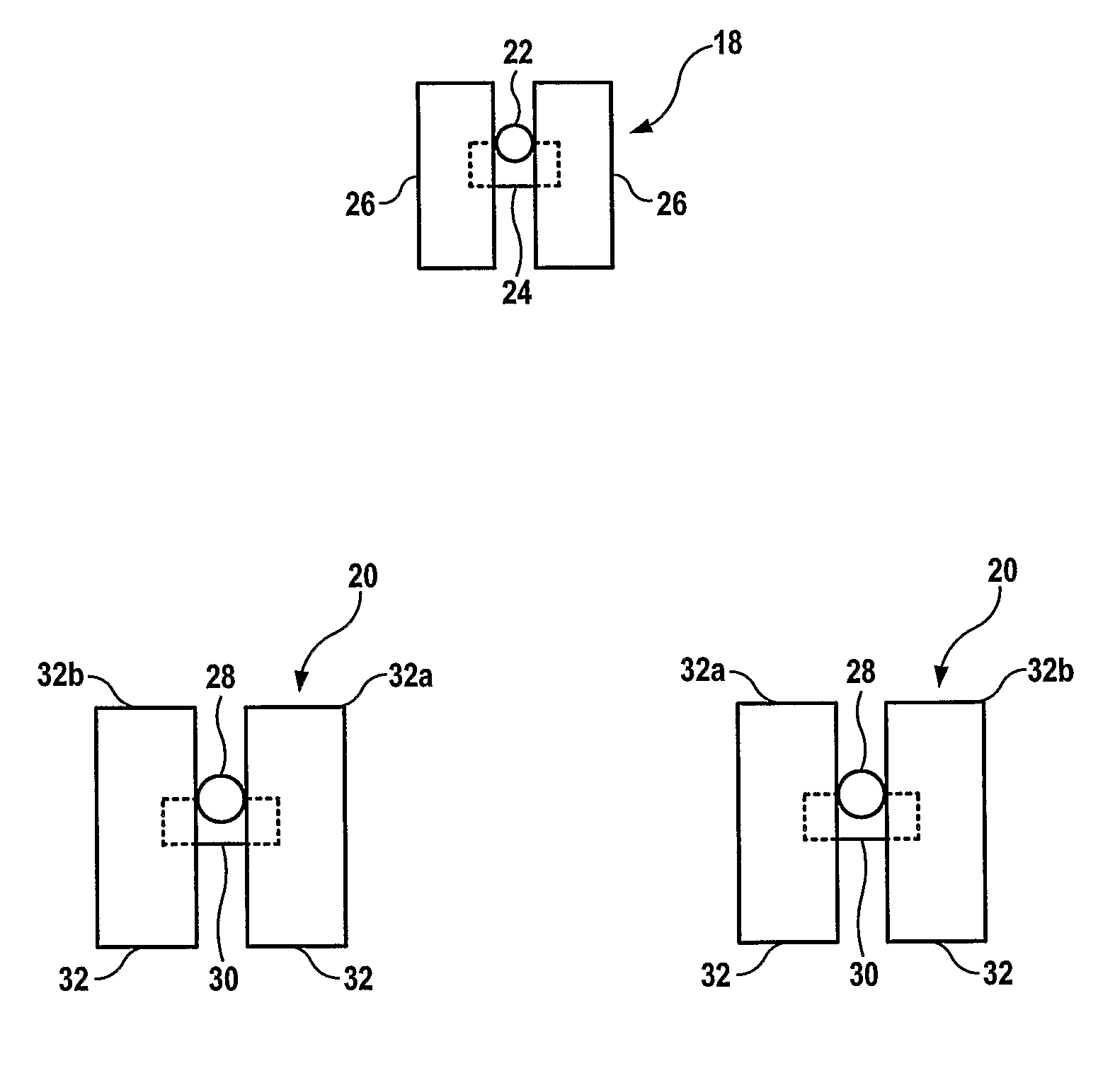
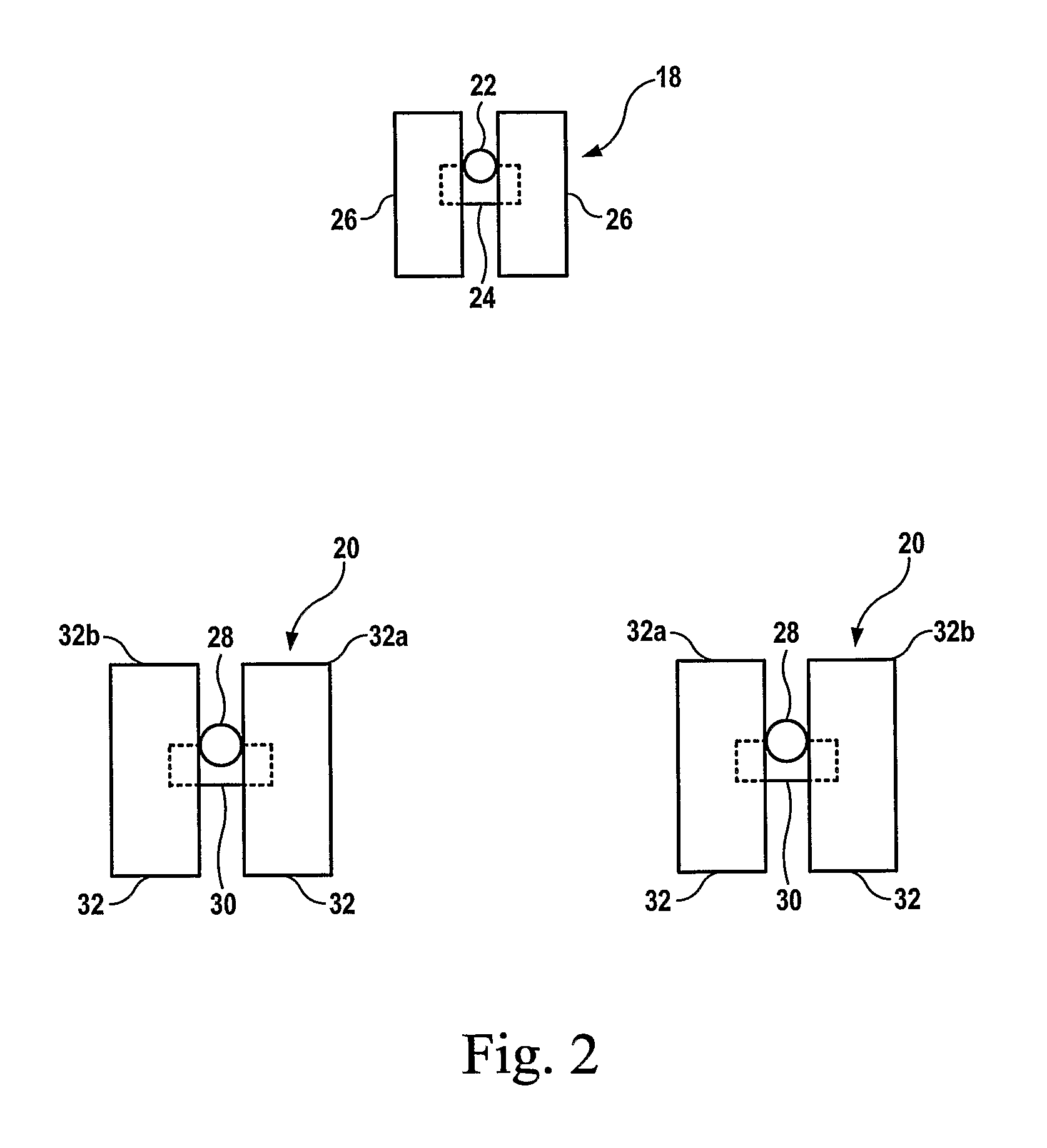
[0023]FIG. 2 illustrates an aircraft landing gear assembly in accordance with the invention in schematic plan form. In FIG. 2, the nose landing gear comprises a retractable landing gear stay 22 which carries an axle 24. The axle 24 has opposite ends which, respectively, mount nose landing gear wheels 26. The nose landing gear wheels 26 are shown in more detail in FIG. 5.

[0024]Each main landing gear assembly 20 comprises a main landing gear stay 28 which carries a main landing gear axle 30. The main landing gear axle 30 has opposite ends which carry, rotatably, main landing gear wheels 32.

[0025]In a conventional main landing g...


PUM


Abstract

An aircraft landing gear arrangement comprises a nose landing gear assembly and at least one main landing gear assembly. The nose landing gear assembly has a nose landing gear wheel with a high energy brake apparatus therein. The main landing gear assembly has a main landing gear wheel with a high energy brake apparatus therein and a main landing gear wheel with a motor therein. The motor is used for driving the main landing wheel during taxiing of the aircraft.

Description

FIELD OF THE INVENTION[0001]The present invention relates to an aircraft landing gear arrangement particularly but not exclusively for use in a so-called tricycle aircraft landing gear arrangement with a single nose landing gear assembly and two spaced main landing gear assemblies.BACKGROUND OF THE INVENTION[0002]When aircraft are moved on the ground they are conventionally either towed by a tow tractor or are powered by the propulsive force of their own main engines (i.e. the same engines that are used during flight).[0003]As aircraft engines are optimised for the flight phase of their operation it is recognised that it would be desirable to reduce the use of the main engines to propel the aircraft on the ground. More specifically, there is believed to be a direct fuel burn saving to an aircraft if the engines are not running during the taxi phase. There may also be an additional gain in efficiency from more accurately predicting the fuel consumption during taxi phase and thereby e...

Claims


Application Information

Patent Timeline
IPC IPC(8): B64C25/40B64C25/42
CPCB64C25/405Y02T50/823B64C25/42Y02T50/80B64C25/10B64C25/34
Inventor WILSON, FRASER
Owner AIRBUS OPERATIONS LTD
Why Eureka
Try Eureka