Stepping motor

Active Publication Date: 2011-04-21
MINEBEAMITSUMI INC
View PDF11 Cites 13 Cited by
  • Summary
  • Abstract
  • Description
  • Claims
  • Application Information

AI Technical Summary

Benefits of technology

In stepping motor structured as described above, since the plurality of terminals, each of which includes the first terminal portion to which one of two wire ends of the winding is connected and the second terminal portion which is disposed parallel to the first terminal portion and to which the driving circuit is connected, are arranged in a line along the direction orthogonal to the axial direction, the axial length of the stepping motor can be reduced. Also, since the first terminal portion and the second terminal portion are aligned along the direction substantially parallel to the axial direction (terminal alignment direction), the distance between the first and second terminal portions can be increased without the necessity of increasing the dimension of the stepping motor measured along the direction orthogonal to the axial direction, which allows an easier work of winding a wire around the first terminal portion using an automatic winding machine.
With the structure described above, when a magnet wire is wound around the plurality of pole teeth thereby forming the winding, the terminal (specifically the second terminal portion) does not hinder the winding work thus improving the workability of forming the winding.
With the structure described above, the distance between the terminals of each of the first and second stator units can be increased. Consequently, when the end of the magnet wire is wrapped on one terminal, the other terminal does not hinder the wrapping work thus further improving the workability of forming the winding.
With the structure described above, the terminal alignment direction can be set with an enhanced precision.

Problems solved by technology

Consequently, the thickness of a circular ring shaped base portion of the yoke must also be reduced, and the axial direction dimension of a terminal block formed at the outer circumference of the base portion of the yoke (inner yoke) is accordingly reduced, which results in making it difficult for the terminals to be arranged in two arrays in the axial direction.
In order to cope with the difficulty, the thickness of a flange of a bobbin may be increased as one solution, but this hinders reduction of the stepping motor in the axial direction and does not necessarily make an acceptable solution.

Method used


Image

  • Stepping motor
  • Stepping motor
  • Stepping motor

Examples


Embodiment Construction

An exemplary embodiment of the present invention will hereinafter be described with reference to the accompanying drawings.

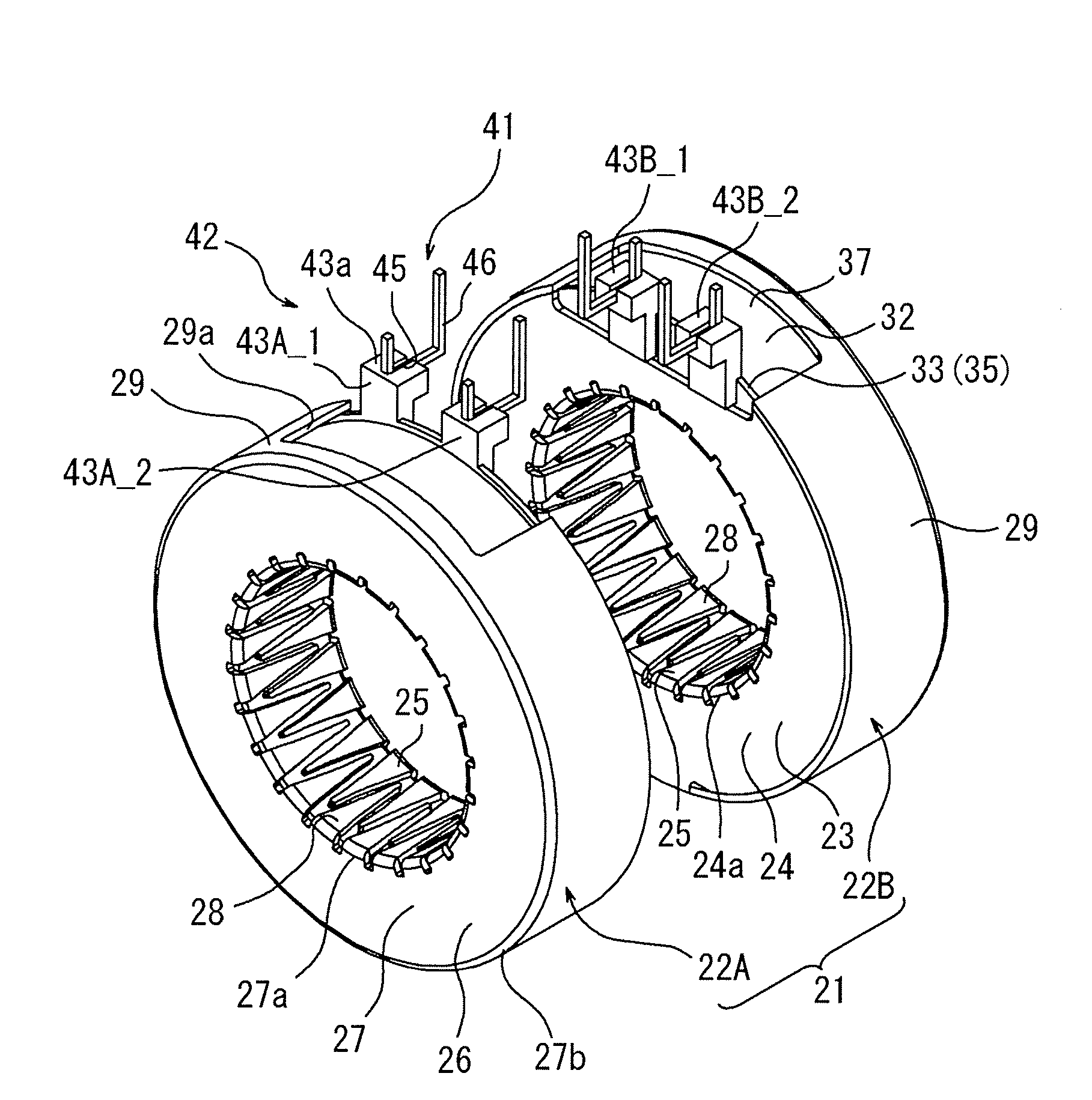
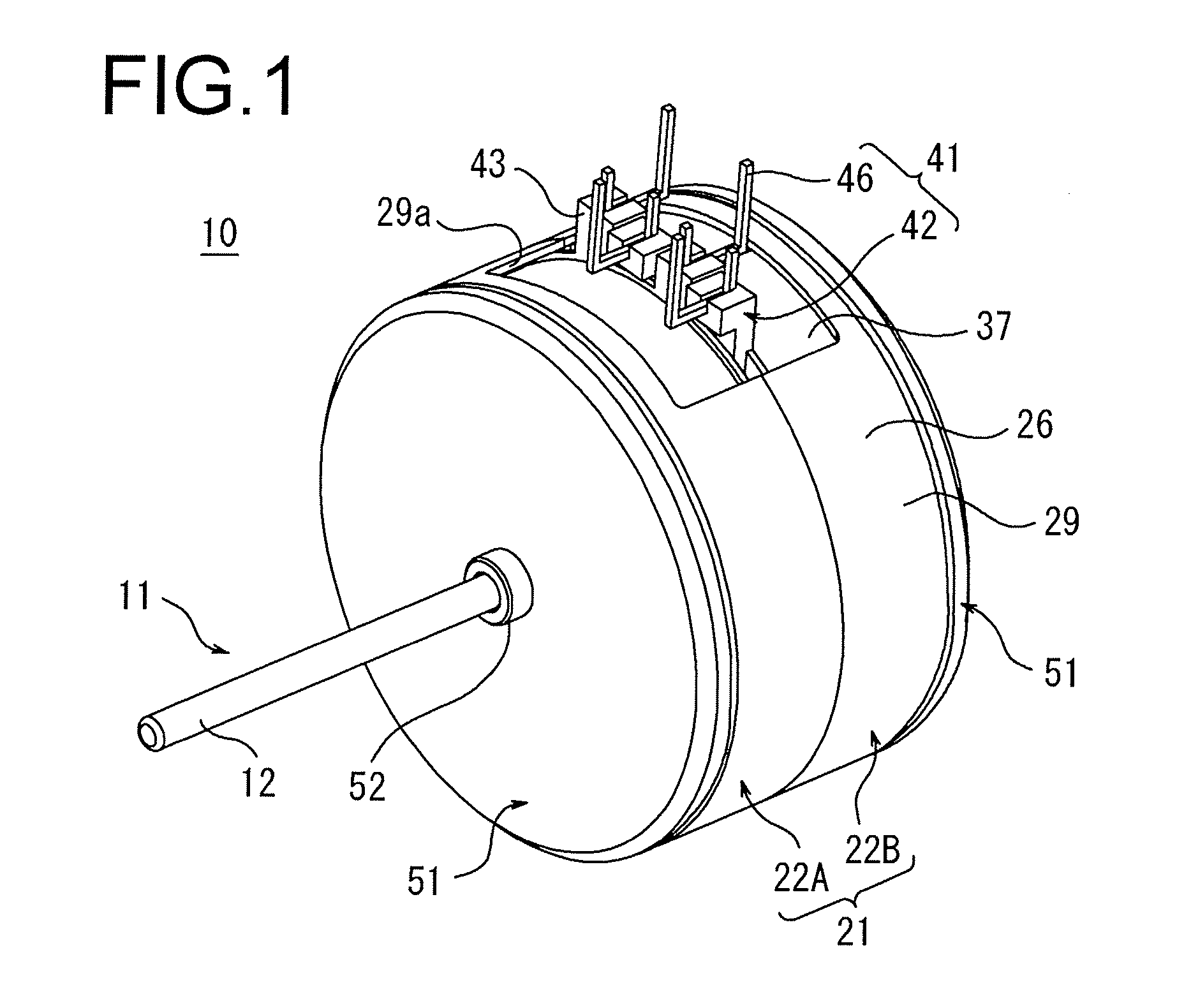
Referring to FIG. 1, a stepping motor 10 according to an embodiment of the present invention includes a circular cylindrical rotor assembly 11 disposed at the center of a rotation axis, an annular cylindrical stator assembly 21 disposed around the rotor assembly 11 with a predetermined gap from the outer circumference of the rotor assembly 11, and a terminal structure (structure for external connection) 41 disposed at the axially central portion of the outer circumference of the stator assembly 21.

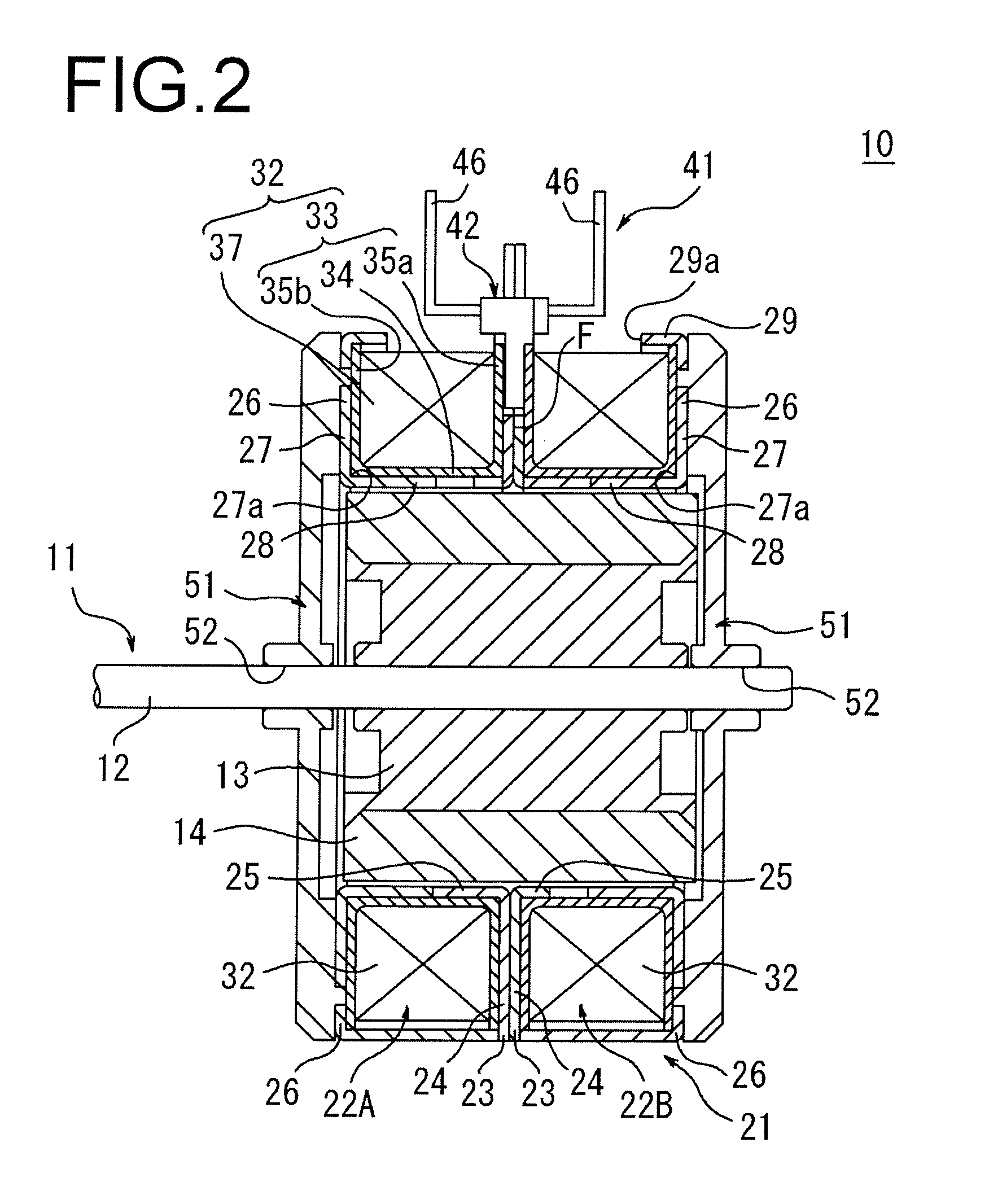
Referring to FIG. 2, the rotor assembly 11 includes a rotary shaft 12 made of a round metal bar, and a cylindrical magnet 14 fixedly attached via a spacer 13 to the outer circumference of the rotary shaft 12 and having a plurality (forty eight in the present embodiment) of magnetic poles arranged circumferentially. The rotary shaft 12 is rotatably supported by a pair o...


PUM


Abstract

A stepping motor includes: a cylindrical rotor assembly disposed around the rotation axis; a stator assembly including two stator units disposed around the rotor assembly and axially coupled to each other; and a terminal structure disposed at the axial center of the outer circumference of the stator assembly. The terminal structure includes: a terminal block cluster composed of four terminal blocks; and four terminals fixed respectively to the four terminal blocks. The four terminals each include: an internal connection portion to which one of two wire ends of the winding is connected; and an external connection portion which is disposed substantially parallel to the internal connection portion and which is connected to a driving circuit disposed externally. The four terminals are arranged in a line along a direction substantially orthogonal to the rotation axis, and the internal connection portion and the external connection portion are aligned along the rotation axis.

Description

BACKGROUND OF THE INVENTION1. Field of the InventionThe present invention relates to a PM stepping motor, and more particularly to a terminal structure of a PM stepping motor.2. Description of the Related ArtA PM (permanent magnet) stepping motor (hereinafter referred to simply as “stepping motor”) includes a rotor assembly including a circular cylindrical magnet having a plurality of magnetic poles disposed circumferentially, and a stator assembly including two stator units axially coupled to each other and disposed around the rotor assembly. Each of the two stator units includes a pair of yokes (inner and outer yokes) which each include a circular ring shaped base portion and a plurality of pole teeth disposed along the inner circumference of the base portion, bent upright and arranged in a comb-like manner, and which are disposed to oppose each other such that respective plurality of pole teeth mesh with each other, wherein a coil for exciting the pair of yokes is disposed around...

Claims


Application Information

Patent Timeline
IPC IPC(8): H02K37/14H02K3/00
CPCH02K37/14H02K3/525
Inventor KINPARA, SHUHEISUZUKI, YUZURU
Owner MINEBEAMITSUMI INC
Why Eureka
Try Eureka