Method for Ground Improvement With Hardened Inclusions

a technology of inclusions and ground, applied in the field of ground improvement with inclusions, can solve the problems of large waves, inducing large waves, and expensive dewatering or shoring to stabilize excavation, and achieve the effect of increasing the tip resistance and increasing the tip resistance valu

Active Publication Date: 2011-04-21
GEOPIER FOUND CO INC
View PDF14 Cites 3 Cited by
  • Summary
  • Abstract
  • Description
  • Claims
  • Application Information

AI Technical Summary

Problems solved by technology

Deep foundations are often relatively expensive when compared to other construction methods.
This method is advantageous because it is performed with conventional earthwork methods, but has the disadvantages of being costly when performed in urban areas and may require that costly dewatering or shoring be performed to stabilize the excavation.
While deep dynamic compaction may be economical for certain sites, it has the disadvantage that it induces large waves as a result of the weight hitting the ground.
These waves may be damaging to structures.
The technique is deficient because it is only applicable to a small band of soil gradations (particle sizes) and is not suitable for materials with appreciable fine-sized particles.
However, this technique has the disadvantages of requiring casing in granular soils with collapsing holes and of necessitating the filling of the holes prior to tamping.
When theoretically applied to multiple holes at once, the system is limited to very shallow treatment depths such as those needed for improvement below pavements.

Method used


Image

  • Method for Ground Improvement With Hardened Inclusions
  • Method for Ground Improvement With Hardened Inclusions
  • Method for Ground Improvement With Hardened Inclusions

Examples


example i

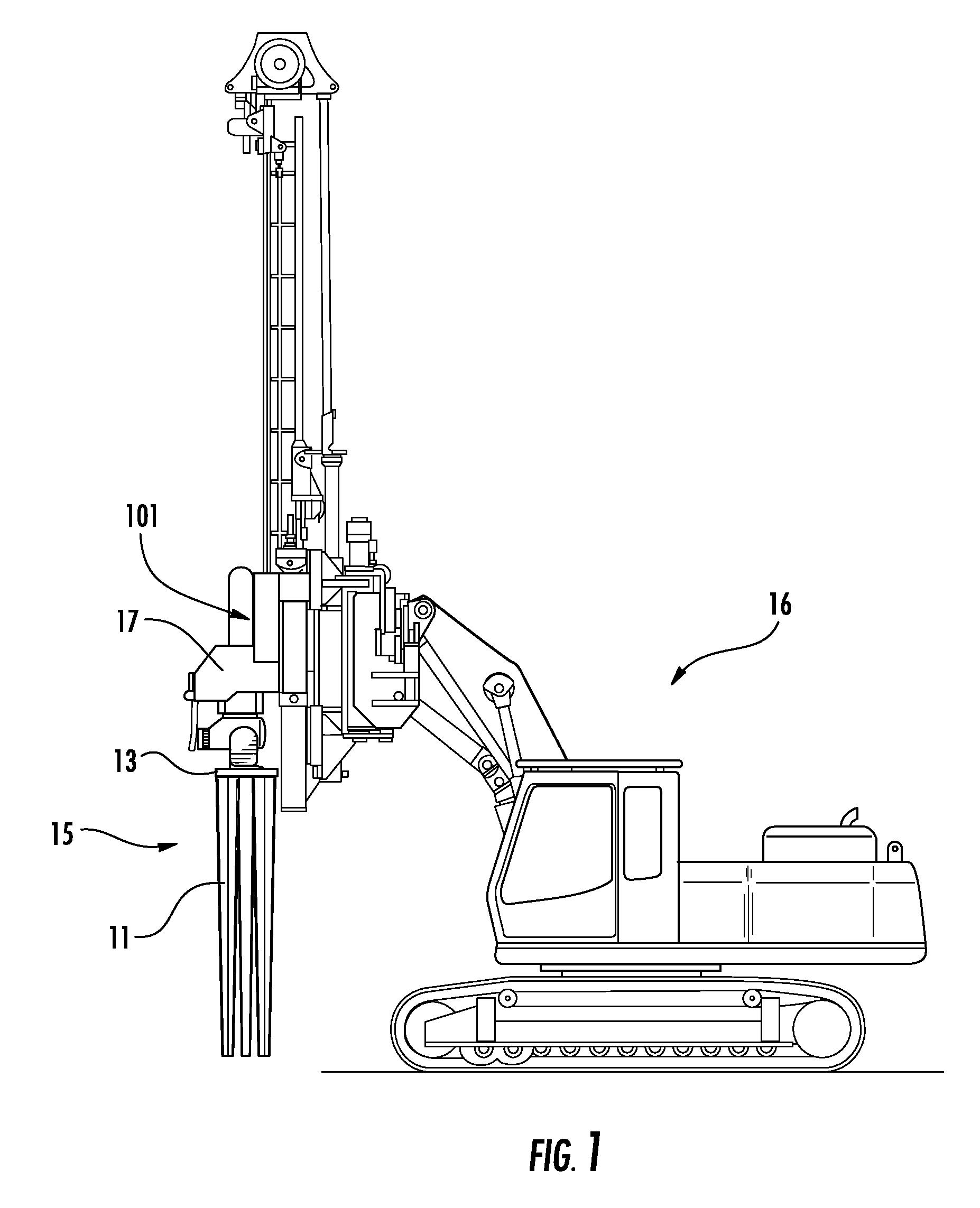
[0051]In May of 2009, testing was performed using a first embodiment of the invention at an Iowa Test Site. The device was used to stabilize natural sand, natural silty sand, and imported fill sand at the site. The device 15 of the invention was advanced at a total of 36 locations. The device 15 was advanced to a depth of 6 feet in all cases. This testing program was used to evaluate the quantitative improvements using the device 15, in comparison to surface compaction with a vibratory plate applied at the ground surface.

Installations

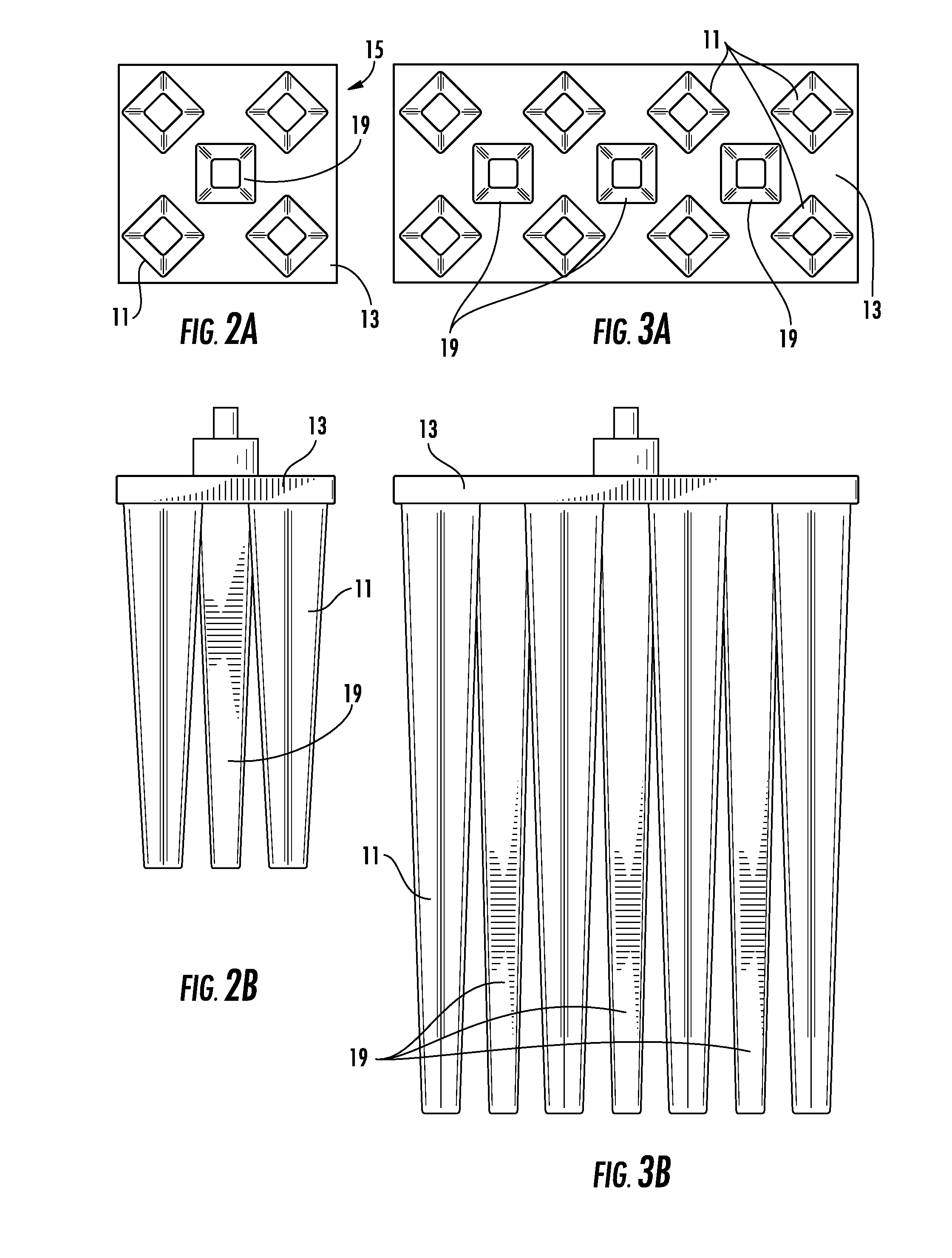
[0052]The device used in this Example I was fabricated to reflect the features shown in FIGS. 2A and 2B. In accordance with the device shown in the figures, five 6-foot long tines 11 were welded to a top plate 13. The tines 11 were fabricated using a square cross-sectional shape tapered upward from a width of 5 inches at the bottom of the tines, to a width of 8 inches at the top of the tines 11. The tines 11 were welded to a 30-inch square top plate 13....

example ii

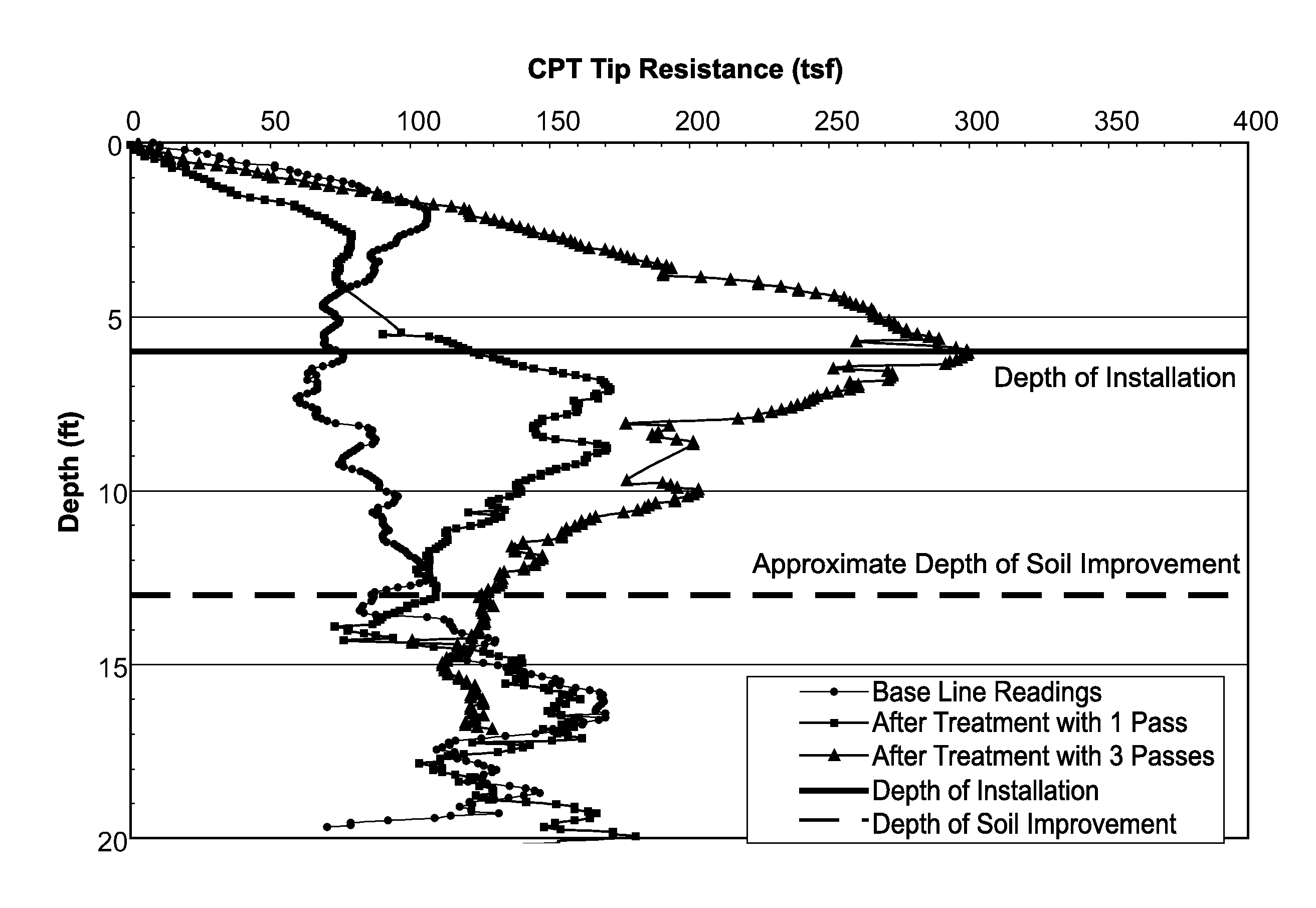
[0064]In July of 2009, additional installations and testing were performed at the Iowa Test Site as described in Example I above. An alternate embodiment of the device 15 was advanced at a total of 22 locations, as described below. The device was advanced to a depth of 10 feet in all cases.

Installations

[0065]The embodiment used in this Example II is shown in FIGS. 3A and 3B and is a device having eleven individual tines 11 attached to an approximately 30-inch by 60-inch top plate 13, with eight tines 11 spaced from each other along the periphery of the top plate 13 and three central tines 19 spaced from each other in an interior region of top plate 13. As in the previous example, a grab plate (not shown) was welded to the top plate, allowing use with a vibratory hammer (amongst others). Each of the tines was 10 feet long, with a 4-inch by 4-inch square bottom transitioning to an 8-inch by 8-inch square top where they connected to the top plate 13. The perimeter or periphery tines 11...

example iii

[0073]In November of 2009, additional testing was performed at the Iowa Test Site as described in Example I above. A new embodiment of the invention was advanced at a total of 10 locations, as described below. The device 15 was advanced to a depth of 20 feet in all cases, unless refusal was encountered. The intention of this testing program was to evaluate the quantitative improvements using the new embodiment.

Installations

[0074]The new embodiment in this Example III was a device 15 including eight individual tines 11 attached to an approximately 30-inch by 45-inch top plate 13 as shown in FIGS. 4A and 4B. The individual tines 11 were each 20 feet long, with a 4-inch by 4-inch square bottom transitioning to an 8-inch by 8-inch square top where they connect to the top plate 13. The transition was accomplished approximately half-way up the tine length. A grab plate was welded to the top plate, allowing use with a vibratory hammer.

[0075]For all of the embodiments, the perimeter tines 1...


PUM

PropertyMeasurementUnit
angleaaaaaaaaaa
angleaaaaaaaaaa
lengthaaaaaaaaaa

Abstract

A method for ground improvement with hardened inclusions includes providing a device having a plurality of tines extending downwardly from a top plate in a manner to achieve displacement of ground material downward and radially outward. The device is mechanically driven into the ground to achieve predetermined depths of penetration by the tines and to create cavities at the location the tines are advanced. The device is at least partially retracted and hardening cementitious material backfill is added into the cavities for forming a plurality of hardened inclusions within the cavities.

Description

CROSS-REFERENCE TO RELATED APPLICATIONS[0001]This patent application is a continuation of, is related to, and claims priority to U.S. patent application Ser. No. 12 / 792,258, filed Jun. 2, 2010, which is related to and claims priority to U.S. Provisional Application Ser. No. 61 / 219,814, filed Jun. 24, 2009. The entire disclosures of said applications are specifically incorporated by reference herein.FIELD OF THE INVENTION[0002]The present invention is related to a method for improving the strength and stiffness of soil by treating the soil with a displacement device having a plurality of tines, and optionally subsequently filling voids made by the device with flowable media such as, for example, sand, gravel, recycled materials, waste materials, tire chips, cement, grout, concrete, or other cementitious material in order to form hardened inclusions in the improved ground area.BACKGROUND OF THE INVENTION[0003]Heavy or settlement-sensitive facilities that are located in areas containin...

Claims


Application Information

Patent Timeline
Patent Type & Authority Applications(United States)
IPC IPC(8): E02D3/12
CPCE02D3/046E02D3/123E02D3/054
Inventor MAHER, STEPHEN A.WISSMANN, KORD J.
Owner GEOPIER FOUND CO INC
Why Eureka
Try Eureka