Surgical head clamp

a head clamp and surgical technology, applied in the field of surgical head clamps, can solve problems such as challenges and constraints, and achieve the effect of avoiding complications

Inactive Publication Date: 2011-04-21
HYBEX HLDG
View PDF15 Cites 11 Cited by
  • Summary
  • Abstract
  • Description
  • Claims
  • Application Information

AI Technical Summary

Benefits of technology

[0007]The present invention relates to a clamping device for firm attachment to a patient's body during medical procedures and for firmly and precisely positioning and orienting instruments attached to the clamping device. One aspect of the present invention involves a clamping device for firm attachment to a patient's head or other location of the patient's body during surgery or other medical procedures and for firmly and precise...

Problems solved by technology

The forgoing creates challenges and constraints for a clamping device for firm attachment to a head or other b...

Method used


Image

  • Surgical head clamp
  • Surgical head clamp
  • Surgical head clamp

Examples


Embodiment Construction

[0026]The description which follows and the embodiments described therein are provided by way of illustration of an example, or examples, of particular embodiments of the principles of the present invention. These examples are provided for the purposes of explanation, and not limitation, of those principles and of the invention. In the description which follows, like parts are marked throughout the specification and the drawings with the same respective reference numerals.

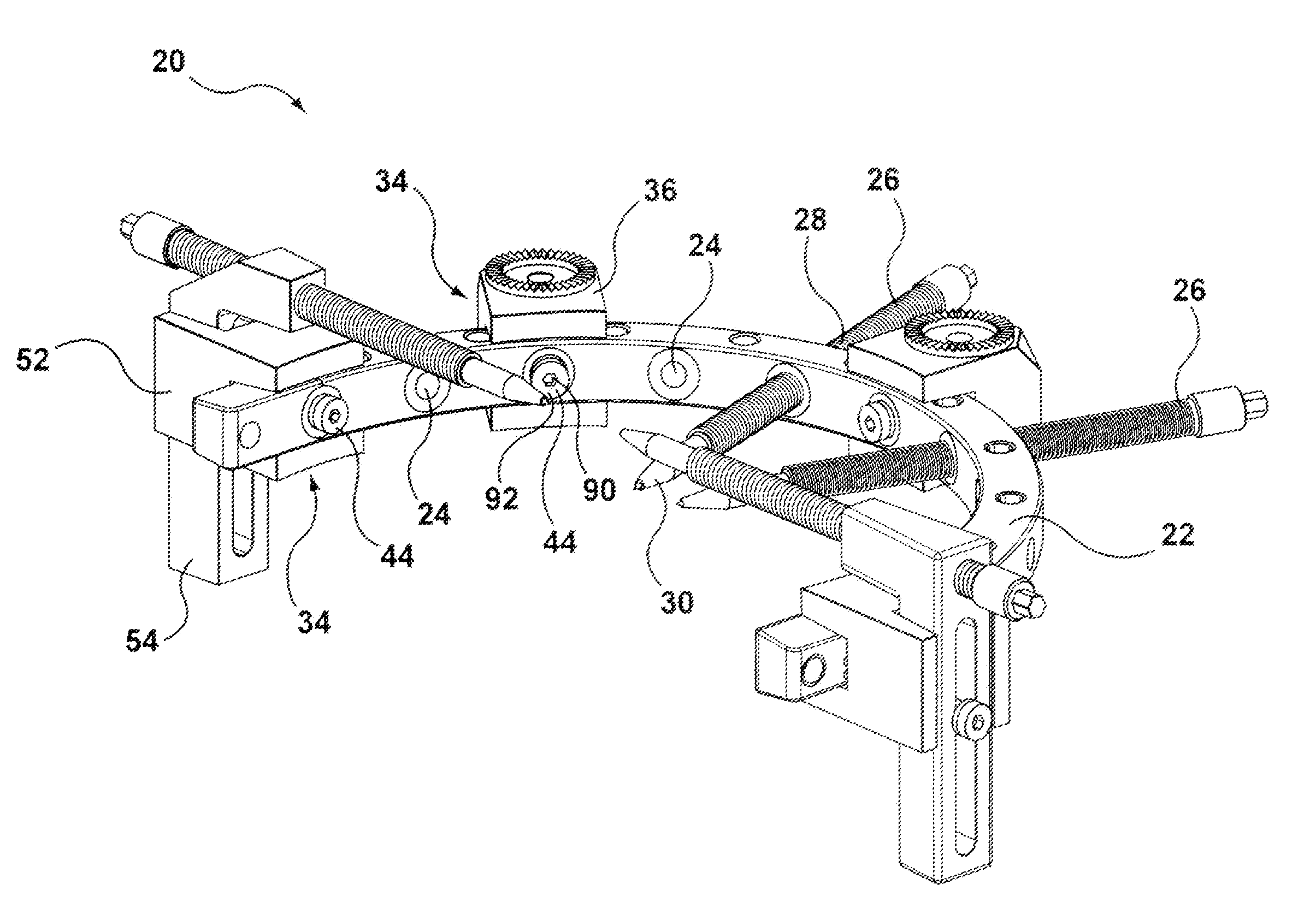
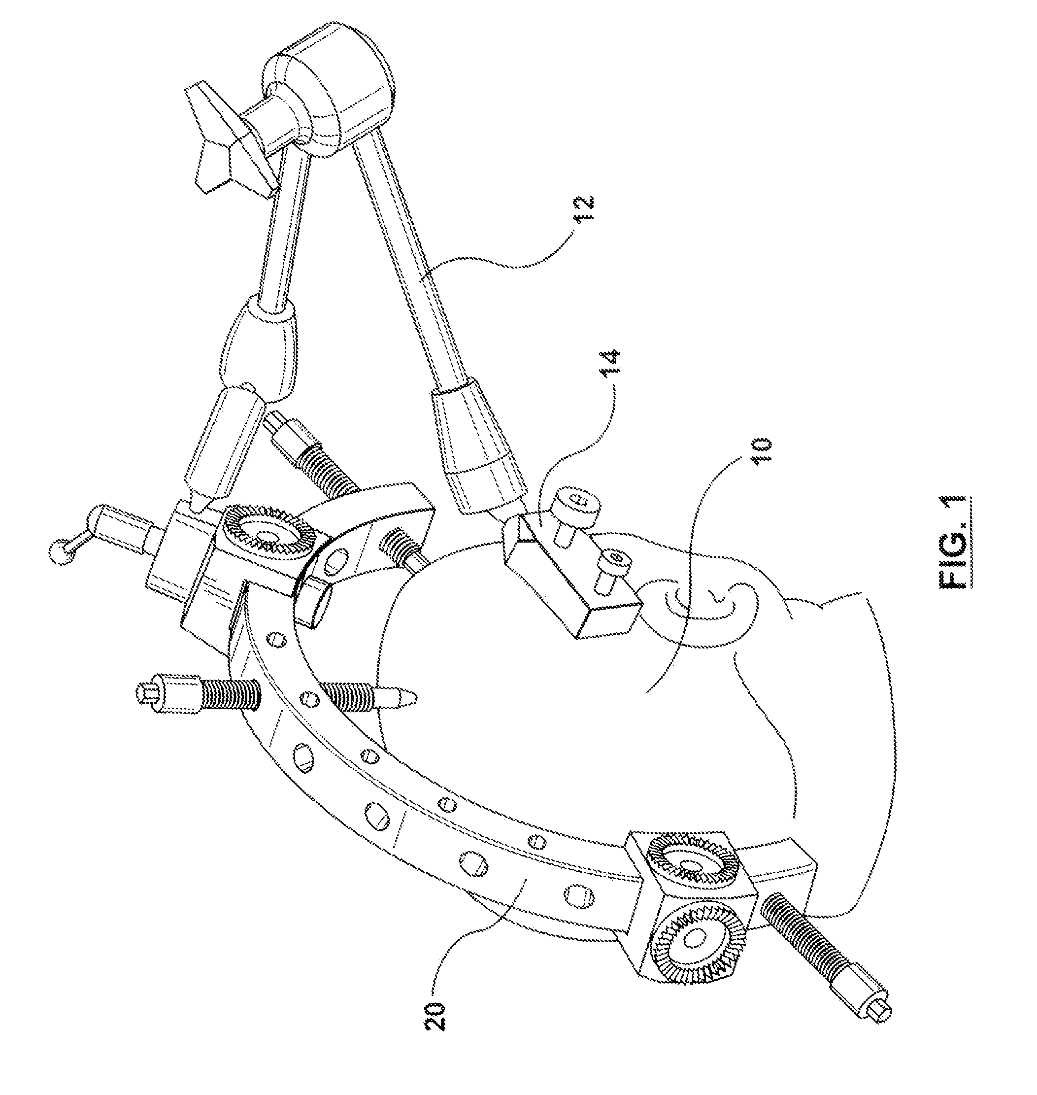
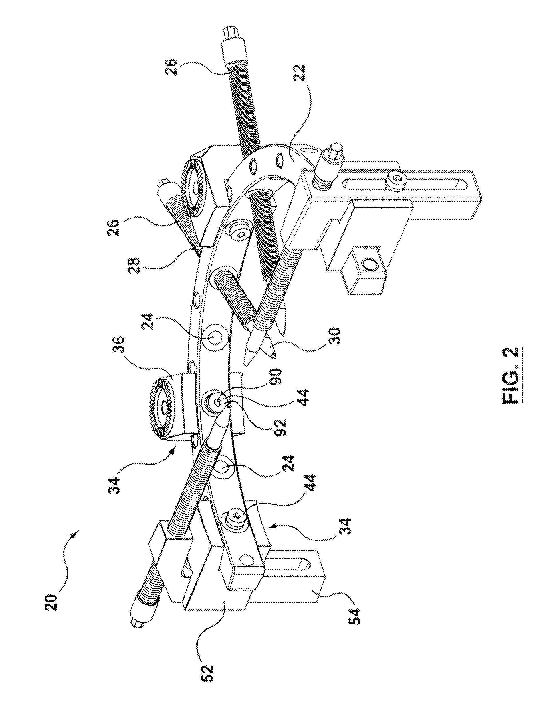
[0027]In the description reference may be made to the general environment of a clamping device. By way of a general overview, FIG. 1 shows in a perspective view a clamping device such as head clamp 20 firmly attached to a patient's head 10. Mounted to the head clamp is an articulated, surgical arm 12 for carrying a medical device, such as probe 14. FIG. 2 shows in another perspective view a head clamp 20 like that shown in FIG. 1, with the articulated arm 12 removed for better illustration.

[0028]Head clamp 20 has a...


PUM


Abstract

The invention relates generally to apparatus and devices for stereotactic surgery, computer aided surgery and other similar medical procedures. More particularly, a clamping device for firm attachment to a body part during surgery and for firmly and precisely positioning and orienting medical instruments attached to the clamping device is disclosed.

Description

CROSS-REFERENCE TO RELATED APPLICATIONS[0001]This application claims priority from U.S. Provisional Application No. 61 / 252,003 filed on Oct. 15, 2009, hereby incorporated by reference.FIELD OF INVENTION[0002]The invention relates generally to apparatus and devices for stereotactic surgery, computer aided surgery and other similar medical procedures. More particularly, a clamping device for firm attachment to a head and for firmly and precisely positioning and orienting medical instruments attached to the clamping device is disclosed.BACKGROUND OF INVENTION[0003]During stereotactic surgery, intracranial operations, computer aided tomography imaging, or similar medical procedures, it is generally desirable to precisely position and orient various instruments relative to a patient's skull or other anatomy and to hold the patient's head or other anatomy immobilized relative to a support surface, such as an operating table, an operating chair or such other patient support structures.[000...

Claims


Application Information

Patent Timeline
IPC IPC(8): A61B19/00
CPCA61B19/203A61B2019/268A61B19/26A61B90/50A61B2090/571A61B90/14
Inventor HYNES, BRIAN
Owner HYBEX HLDG
Why Eureka
Try Eureka