Syringe needle guiding apparatus

a technology of guiding apparatus and syringe needle, which is applied in the field of guiding apparatus, can solve the problems of misunderstanding of the positional relationship of the blood vessel, the conventional technique of inserting a syringe needle into a blood vessel requires trial-and-error-like operation, etc., and achieves the effect of improving image quality

Inactive Publication Date: 2011-04-21
NORY CO LTD
View PDF2 Cites 19 Cited by
  • Summary
  • Abstract
  • Description
  • Claims
  • Application Information

AI Technical Summary

Benefits of technology

As mentioned above, the present invention is an apparatus which creates images of a blood vessel and a needle and recognizes the positional relationship between the blood vessel and the needle. From the present invention, the following effects are expected.
1) A blood vessel can be recognized by using a blood vessel image whose image quality is optimized by using a see-through technology and an image processing technique, instead of relying on the sensitivity of the naked eyes.
2) What kind of shapes blood vessels have and how the blood vessels extend and bend, and so forth can be recognized correctly. Therefore, a suitable blood vessel for needle insertion as well as a suitable part of the blood vessel for the insertion can be selected readily.
3) By the blood vessel recognition described above, the type and size of a syringe needle can be selected in advance.
4) A needle's insertion target, direction and angle which allow the needle and the blood vessel to intersect each other in a three-dimensional space can be figured out precisely.
5) A target (distance, insertion angle and direction) of a syringe needle is displayed in real time in synchronization with the directional manipulation and insertion operation of the needle by a person to perform injection. Hence, simple yet accurate insertion of the needle into a blood vessel can be performed only by the guiding using a monitor.

Problems solved by technology

Nonetheless, any of these conventional techniques for inserting a syringe needle into a blood vessel requires trial-and-error-like operation since it relies on uncertain information obtained through the estimation of the location of a blood vessel by observing and / or touching an outer part of a body, as mentioned above.
That is to say, in order to perform injection into a blood vessel, the tip of a needle needs to be fit into and stay inside the blood vessel; however, a planar image alone may lead to a misunderstanding of the positional relationship with the blood vessel.

Method used


Image

  • Syringe needle guiding apparatus
  • Syringe needle guiding apparatus
  • Syringe needle guiding apparatus

Examples


example 1

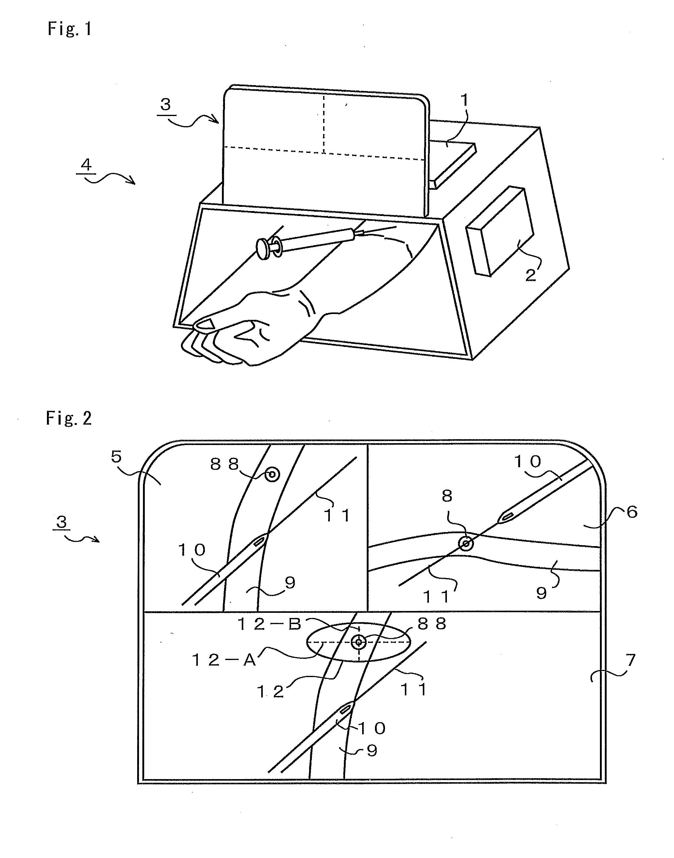
Embodiments of the present invention will be described by referring to the drawings. FIG. 1 is a perspective diagram of an overview of a syringe needle guiding apparatus 4 including built-in cameras, each of which includes a light source of near infrared rays or the like used for capturing images of a blood vessel, and different built-in cameras for capturing images of a syringe and its needle 10.

Each of a planar camera 1 and a lateral camera 2 is a camera functioning as a near infrared camera for capturing an image of a blood vessel as well as a visible light camera for capturing images of a syringe and its needle. The planar camera 1 captures images of a blood vessel 9, the syringe and the needle 10 from above, whereas the lateral camera 2 captures images of the blood vessel 9, the syringe and the needle 10 from a lateral side.

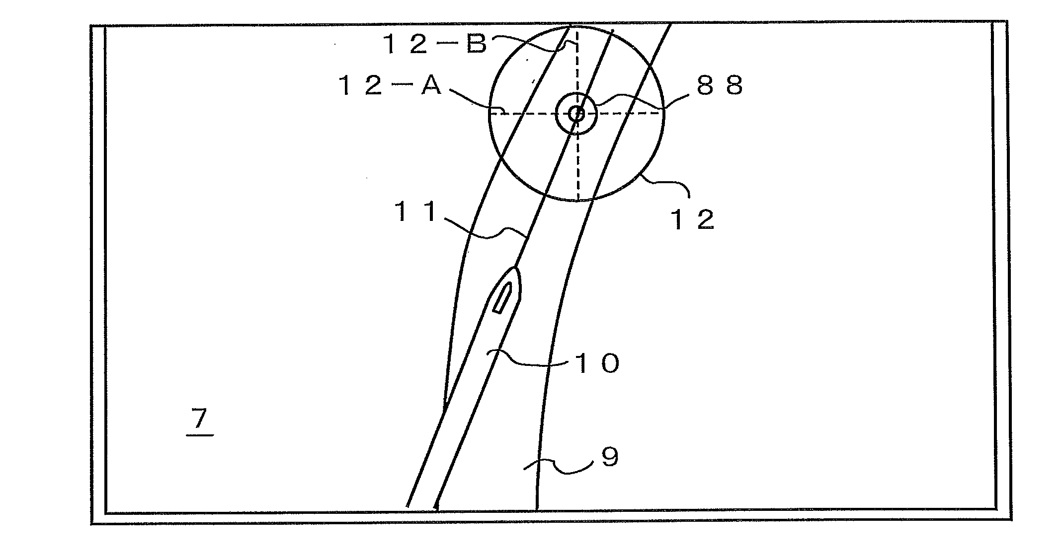
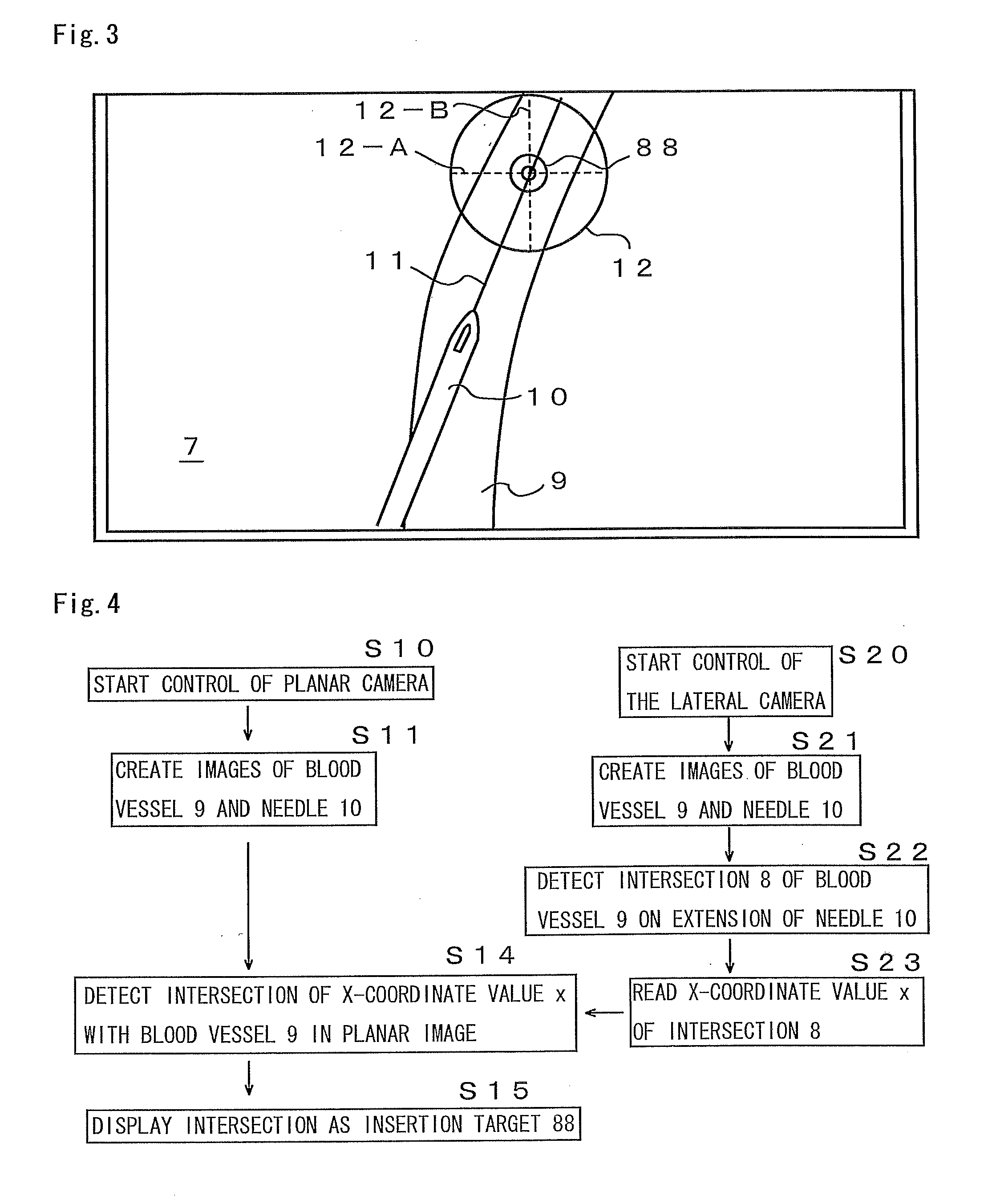
A planar image 5 is an image which is obtained by synthesizing, by using mixed reality technology, images of the blood vessel 9 and the syringe needle 10 ca...

example 2

Example 2 is a case where the monitor for a total image in Example 1 displays a three-dimensional image. Although polarized glasses and / or the like are required, the image data (including the insertion target 88 and the extend line of the needle) of both the planar image 5 and the lateral image 6 is displayed on a three-dimensional display.

Hereinabove, examples are described. However, embodiments reflecting the technical idea of the present invention are not limited to the aforementioned examples. Moreover, the video engine program that automatically recognizes image data such as an insertion target, a distance, an angle and synthesis and makes notification using images can be changed in various ways. The procedure for carrying out the present invention and the claims of the present invention are not to be limited by embodiments of the program and the like.


PUM


Abstract

Provided is a syringe needle guiding apparatus 4 which creates images of a blood vessel 9 which cannot be directly seen with the naked eyes and of a syringe needle 10 inserted into a body, and which includes a monitor 3 allowing the recognition of the three-dimensional relationship between the blood vessel 9 and the needle 10. In the syringe needle guiding apparatus 4 provided here, the blood vessel 9 is seen through by using near infrared rays and also a part of the needle 10, which cannot be seen through because it is inserted into a body, is reproduced in a form of virtual image. A virtually synthesized image of the blood vessel 9 and the needle 10 is displayed on the monitor 3. Then, a target 88 at which the needle 10 is to be inserted, a direction, a distance 12-A, an angle 12-B of the needle with respect to the blood vessel, and the like are displayed in the synthesized image, so that the positional relationship between the blood vessel and the needle 10 is recognized in a three-dimensional manner.

Description

TECHNICAL FIELDThe present invention relates to a guiding apparatus to facilitate the insertion of a syringe needle into a blood vessel.BACKGROUND ARTAs one of the techniques in inserting a syringe needle into a blood vessel in intravenous injection and blood collection, medical doctors and nurses estimate the location of a blood vessel by observing and / or touching skin and insert a needle. A large portion of this technique, relies on the person's experience and intuition. Thus, the goal of needle insertion is not always achieved certainly by the first insertion.A cause of such uncertainty in the technique of inserting a needle into a vein is that some blood vessels inside a body cannot be seen directly, and therefore it is difficult to figure out where they are located, how they extend, what kind of shape they have, and so forth. In addition, another cause is that apart of a syringe needle having been inserted into a body cannot be seen with the naked eyes, and therefore the true p...

Claims


Application Information

Patent Timeline
Patent Type & Authority Applications(United States)
IPC IPC(8): A61B6/00G06K9/00G06T15/00
CPCA61B5/0059A61B5/489A61B17/3403A61B19/5225A61B2019/502A61M5/52A61B2019/5227A61B2019/5265A61B2019/5291A61M5/427A61B2019/507A61B90/37A61B2034/102A61B2034/107A61B2034/2065A61B2090/365A61B2090/371
Inventor YASUI, NORIO
Owner NORY CO LTD
Why Eureka
Try Eureka