
Display device and driving circuit thereof
a technology of a driving circuit and a display device, which is applied in the direction of instruments, digital computers, cathode-ray tube indicators, etc., can solve the problems of deteriorating image inability to increase the cutting ratio of power consumption, and deterioration of image quality of a user interface image, etc., to achieve the effect of increasing compressibility, not noticeably deteriorating image quality, and reducing power consumption
- Summary
- Abstract
- Description
- Claims
- Application Information
AI Technical Summary
Benefits of technology
Problems solved by technology
Method used
Image

Examples
first embodiment
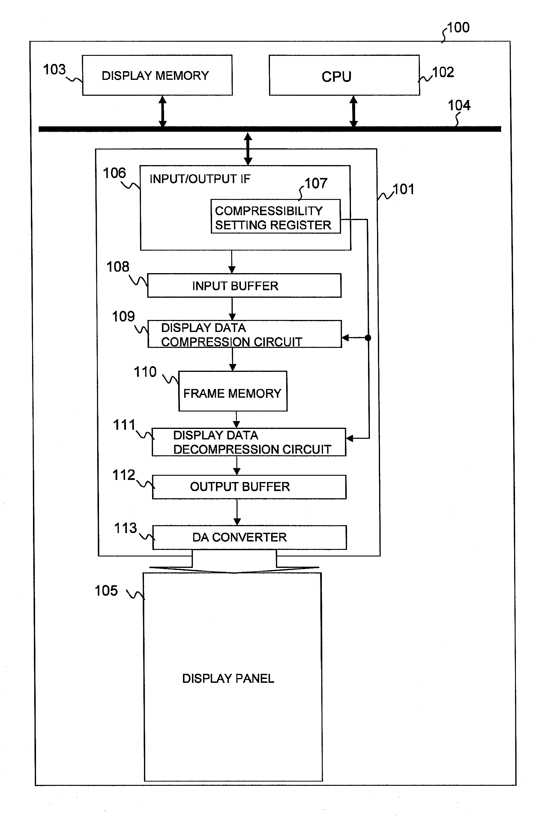
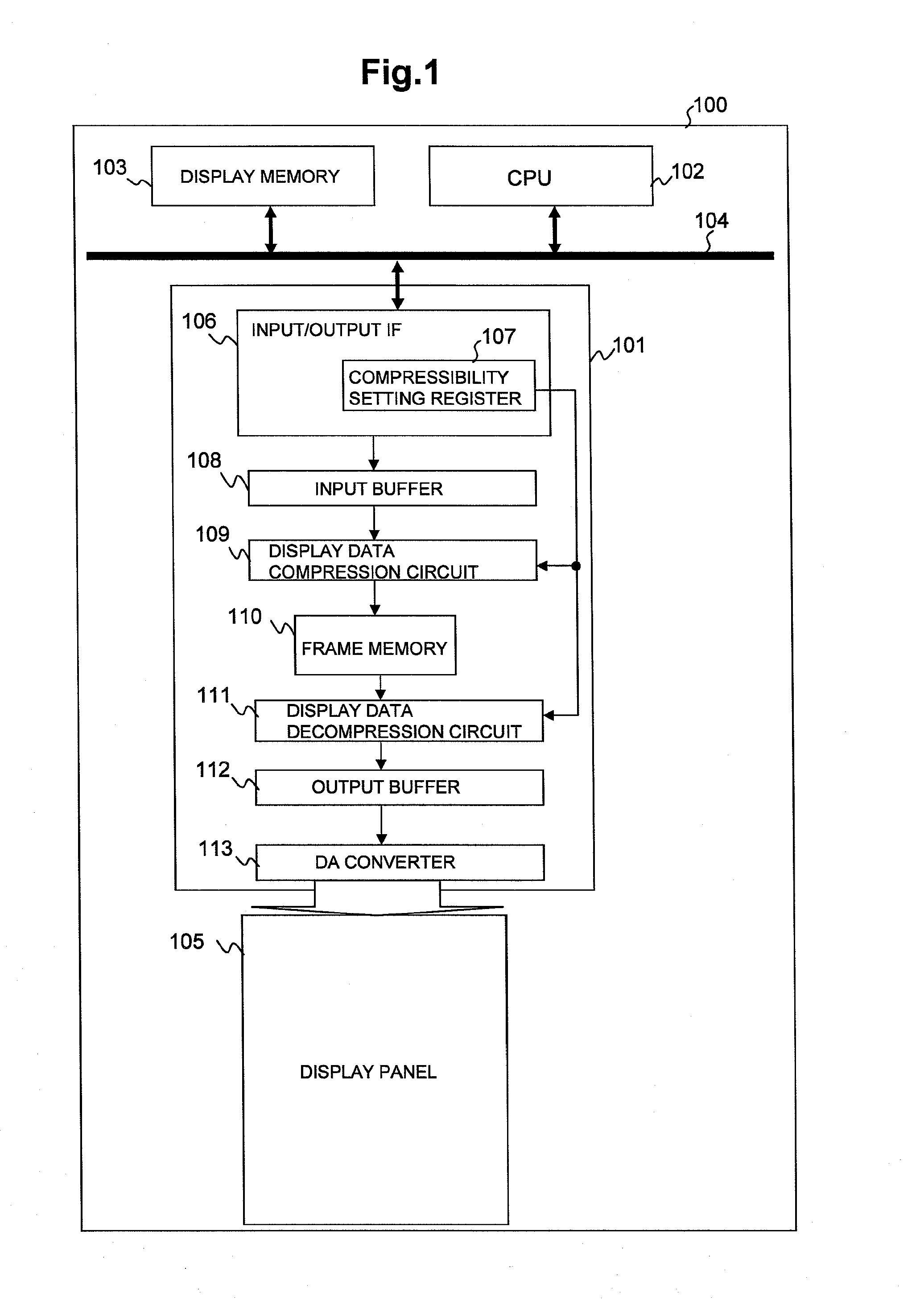
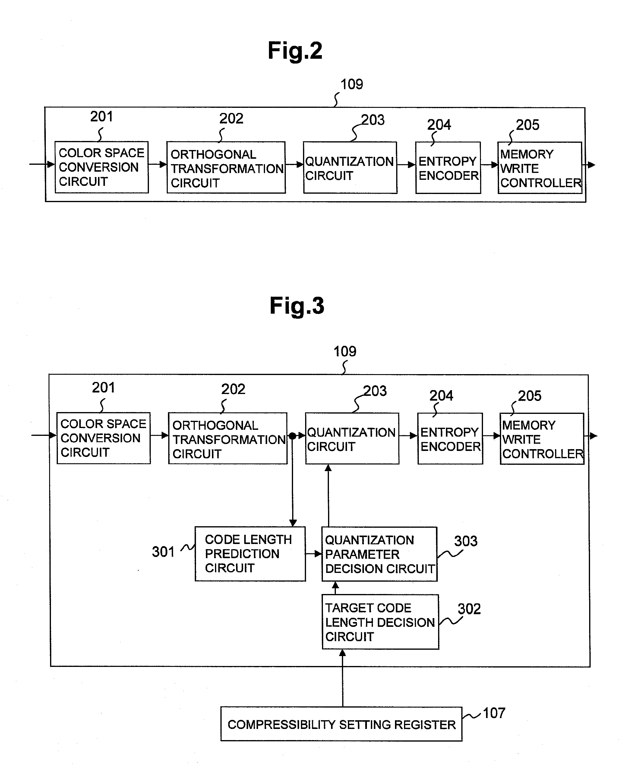
[0060]Next, the first embodiment will be described in detail. FIG. 1 is a block diagram showing a display unit according to the first embodiment of the invention. The reference numeral 100 denotes a display unit of a mobile phone or the like. The numeral 101 denotes a display driver, such as an LC driver. The numeral 102 denotes CPU (Central Processing Unit) which controls, in whole, a display unit such as a mobile phone. The numeral 103 denotes a display memory to store display data, etc. The numeral 104 denotes an internal bus. The numeral 105 denotes a display panel which is driven by the display driver 101 and produces a display. The display panel may be any of an LC panel, an organic EL (Electro-Luminescence) panel, PDP (Plasma Display Panel), FED (Field Emission Display), and an electronic paper, for example.
[0061]The numeral 106 denotes an I / O interface circuit which has a group of registers (not shown) for making settings of various modes, and which receives display data fro...
second embodiment
[0069]Next, the display unit according to the second embodiment of the invention will be described with reference to FIGS. 5 to 8.
[0070]The major difference between the second embodiment and the first embodiment is that in the second embodiment, the display region thereof is parted into two or more areas, and the compressibility can be changed for each area.
[0071]In general, a display screen 501 of a mobile phone or the like, is parted into a standby image 503 of a natural picture, and UI (User Interface) image display areas 502 and 504 where a time display, various kinds of icons and the like are laid out, as shown in FIG. 5.
[0072]FIG. 6 is a block diagram showing the display unit according to the second embodiment. Comparison with the block diagram of FIG. 1 has shown that unlike the display unit according to the first embodiment, the display unit 100 according to the second embodiment has a display-area-setting register 603, and first and second area-compressibility setting regis...
third embodiment
[0076]Now, with reference to FIG. 9, the third embodiment of the invention will be described.
[0077]The major difference between the third embodiment and the first and second embodiments is that in the third embodiment, CPU 102 includes a display data compression circuit 901.
[0078]The display data compression circuit 901 is identical to the display data compression circuit 109 of the display unit according to the first embodiment in function. The display data compression circuit 901 compresses displayed image according to the set value of the compressibility setting register 902 in CPU 102, and transmits the data to the display driver 101 through an internal bus 104. Alternatively, the display data may be sent to the display driver 101 from CPU 102 directly, or otherwise the compressed data may be transferred from CPU 102 to the display memory 103 and stored there once, and then transmitted from the display memory 103 to the display driver 101. At the time of display, CPU 102 sets a ...
PUM
 Abstract
Description
Claims
Application Information