
Map display device and map display method

a map display and map technology, applied in traffic control systems, navigation instruments, instruments, etc., can solve problems such as user difficulty in viewing the display, user may not effectively use the map, and difficulty in viewing the map, so as to achieve the effect of easily and efficiently changing the display position of road-related information

Active Publication Date: 2011-04-21
ALPINE ELECTRONICS INC
View PDF21 Cites 8 Cited by
  • Summary
  • Abstract
  • Description
  • Claims
  • Application Information

AI Technical Summary

Benefits of technology

[0016]The present invention is made to address the disadvantages of the related art, and an object of the present invention is to provide a map display device and a map display method that can change a display position of road-related information easily and efficiently without entirely updating the map data.
[0022]With the map display device and the map display method according to the aspects of the present invention, the display position of the road-related information may be calculated on the basis of the adjustment data information (shift width) indicative of a distance by which the road-related information stored in association with the road data that is shifted from the road when the map is displayed. The road-related information may be displayed on the basis of the calculation result. Accordingly, even if the road width is changed to the road width defined on the basis of the road type and the number of lanes of the road, the display of the road-related information does not overlap the road. The map display can be easily viewed.
[0023]In addition, since the shift width is defined in association with the road, the display position of the road-related information may be determined and the road-related information may be displayed at the determined position when the map is displayed. The map data does not have to be entirely updated. The road-related information can be easily and quickly displayed at the optimal position.

Problems solved by technology

The user may have difficulty in viewing the map, or the user may not effectively use the map.
Thus, the user may have difficulty in viewing the display.
This update may take time and be troublesome.

Method used


Image

  • Map display device and map display method
  • Map display device and map display method
  • Map display device and map display method

Examples


Embodiment Construction

[0034]An embodiment of the present invention will be described below with reference to the attached drawings.

Configuration of On-Vehicle Navigation Device

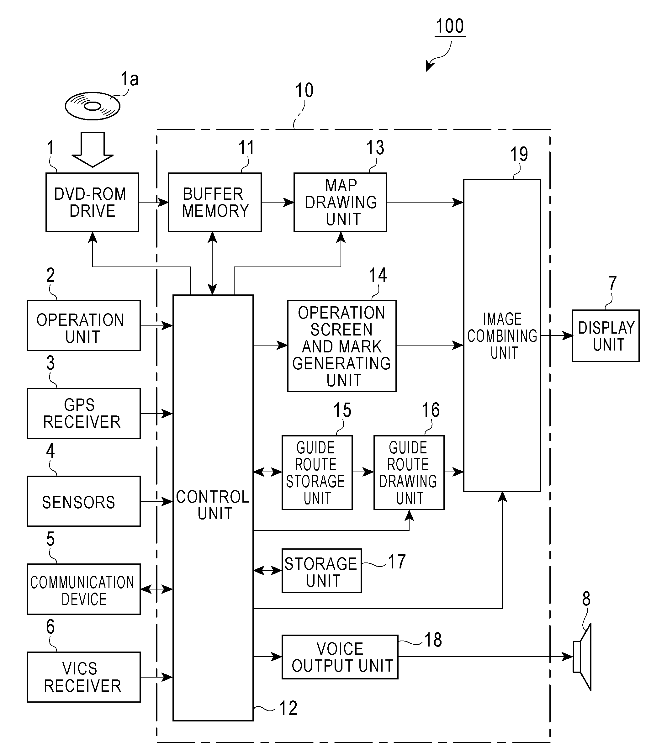
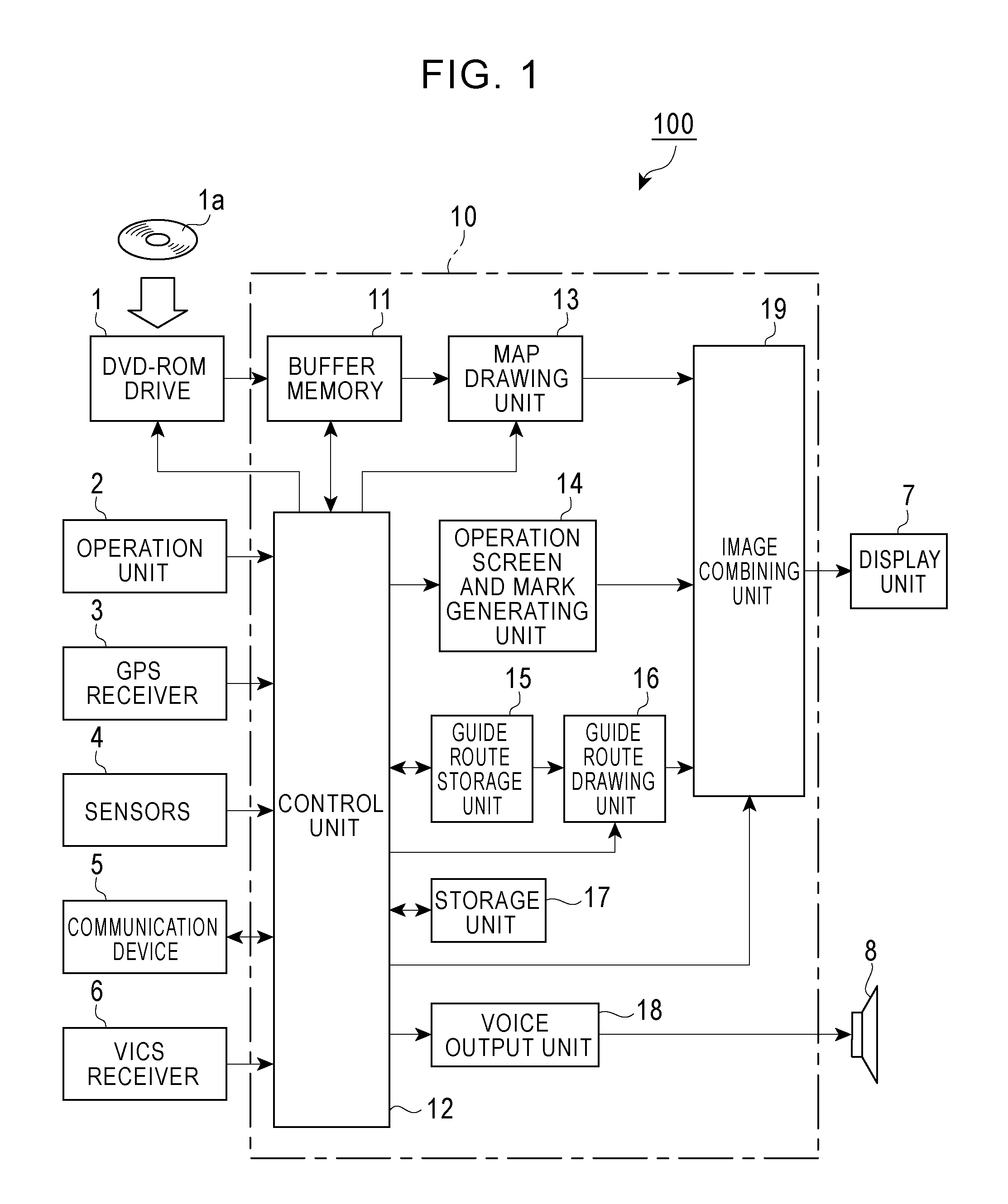
[0035]FIG. 1 is a block diagram of an embodiment for a map display device of the present invention showing a configuration of an on-vehicle navigation device 100 having a function of a map display device.

[0036]Referring to FIG. 1, a DVD-ROM drive 1 is illustrated. A storage medium stores map data and guide data. In this embodiment, the storage medium that stores such data is a DVD-ROM 1a. However, a hard disk or another storage medium may be used. The map stored in the DVD-ROM 1a is divided into longitude widths and latitude widths with proper sizes depending on scales, for example, 1 / 12500, 1 / 25000, 1 / 50000, and 1 / 100000. Various objects including roads, buildings, and facilities in the map are stored as sets of coordinates of nodes, which are expressed with the longitude and latitude. The map data includes (1) a road layer having...


PUM


Abstract

A map display device that displays a map image around a vehicle position includes a display unit; a first storage unit storing map data including road data of a road and road-related information related to the road; a second storage unit storing adjustment data based on a relationship between display positions of the road data and the road-related information; and a map display control unit for calculating the display position of the road-related information based on the adjustment data for the individual road, and displaying the road-related information on a screen of the display unit. A road width to be displayed o the screen may be determined in accordance with the number of lanes and a road type. The adjustment data may be a distance between the display positions of the road and the road-related information, and may be determined in accordance with the road type and the road width.

Description

RELATED APPLICATIONS[0001]The present application claims priority to Japanese Patent Application Number 2009-242055, filed Oct. 21, 2009, the entirety of which is hereby incorporated by reference.BACKGROUND OF THE INVENTION[0002]The present invention relates to a map display device and a map display method, and more particularly to a map display device and a map display method that have a function for displaying a street name at an optimal position in accordance with a road width.DESCRIPTION OF THE RELATED ART[0003]A typical on-vehicle navigation device of related art includes a control device, such as a CPU, that controls all processing related to navigation; a storage device, such as a digital versatile disk read only memory (DVD-ROM) or an integrated circuit (IC) memory card, that previously stores map data; a display device; a global positioning system (GPS) receiver; and detectors, such as a gyro and a vehicle speed sensor, that detect a current position and a current azimuth o...

Claims


Application Information

Patent Timeline
IPC IPC(8): G01C21/32
CPCG01C21/3673
Inventor CHIBA, KAZUOMISATO, YUKIO
Owner ALPINE ELECTRONICS INC
Learn More