
Scalable biomass reactor and method

a biomass reactor and biomass technology, applied in the field of conversion of organic lignocellulosic materials, can solve the problems of equipment adding to system complexity and size, inconvenient use of output gas for gas turbines, storage, etc., and achieves large throughput capacity and efficient production of synthesis gas

Active Publication Date: 2011-04-28
INDIANA UNIV RES & TECH CORP
View PDF8 Cites 3 Cited by
  • Summary
  • Abstract
  • Description
  • Claims
  • Application Information

AI Technical Summary

Benefits of technology

The present invention provides a system and method for efficiently producing synthesis gas from biomass materials at relatively large throughput capacities. The system includes multiple parallel reactors with internal passages, a means for compacting loose biomass and introducing it into the reactors, a means for heating the biomass to a temperature where organic molecules break down to form ash and gases, a means for preventing combustion of the biomass, gas passages for conducting the gases through the reactors in a direction opposite to the movement of the biomass, and a means for removing the ash from the reactor. The method involves compacting the biomass, heating it, inhibiting combustion, conducting the gases through the reactors, and removing the ash. The technical effects of this invention include improved production of synthesis gas from biomass materials and increased throughput capacity.

Problems solved by technology

First, the introduction of air into the hot gasification chamber partly combusts the biomass, yielding a lower overall heating value compared to pure gasification.
Second, if air is used as the gasification agent, nitrogen in the air is a diluent that reduces the energy content per unit volume of the output gas, making the output gas inconvenient for use in gas turbines, for storage, and for subsequent chemical processing.
The removal equipment adds to system complexity and size, with the result that for economic reasons the gasifier is usually limited to large installations.
Because biomass is a low-energy content fuel and is dispersed geographically, a large-scale gasifier requires transport and storage of the biomass, which negatively affects the economic payback for the system.

Method used


Image

  • Scalable biomass reactor and method
  • Scalable biomass reactor and method

Examples


Embodiment Construction

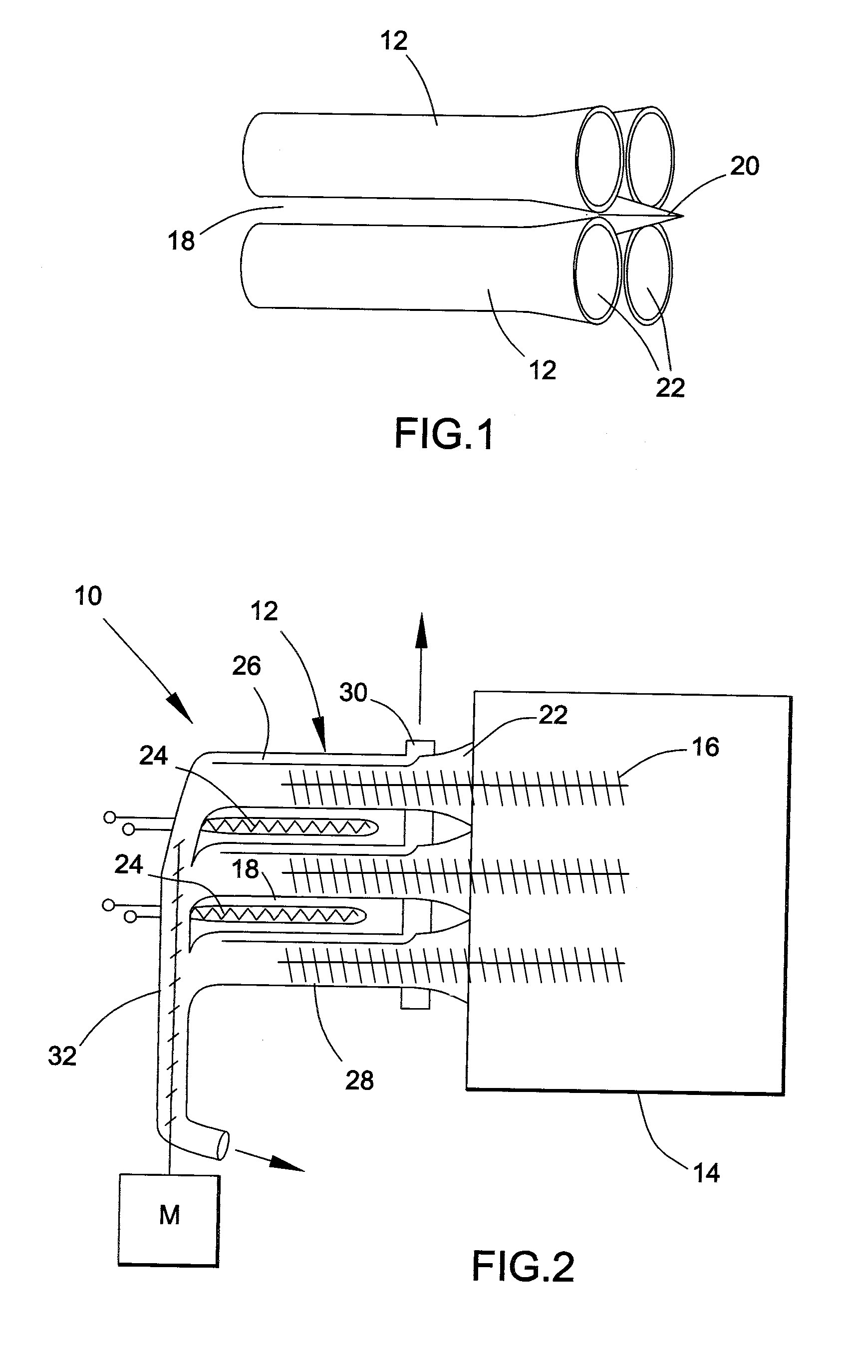
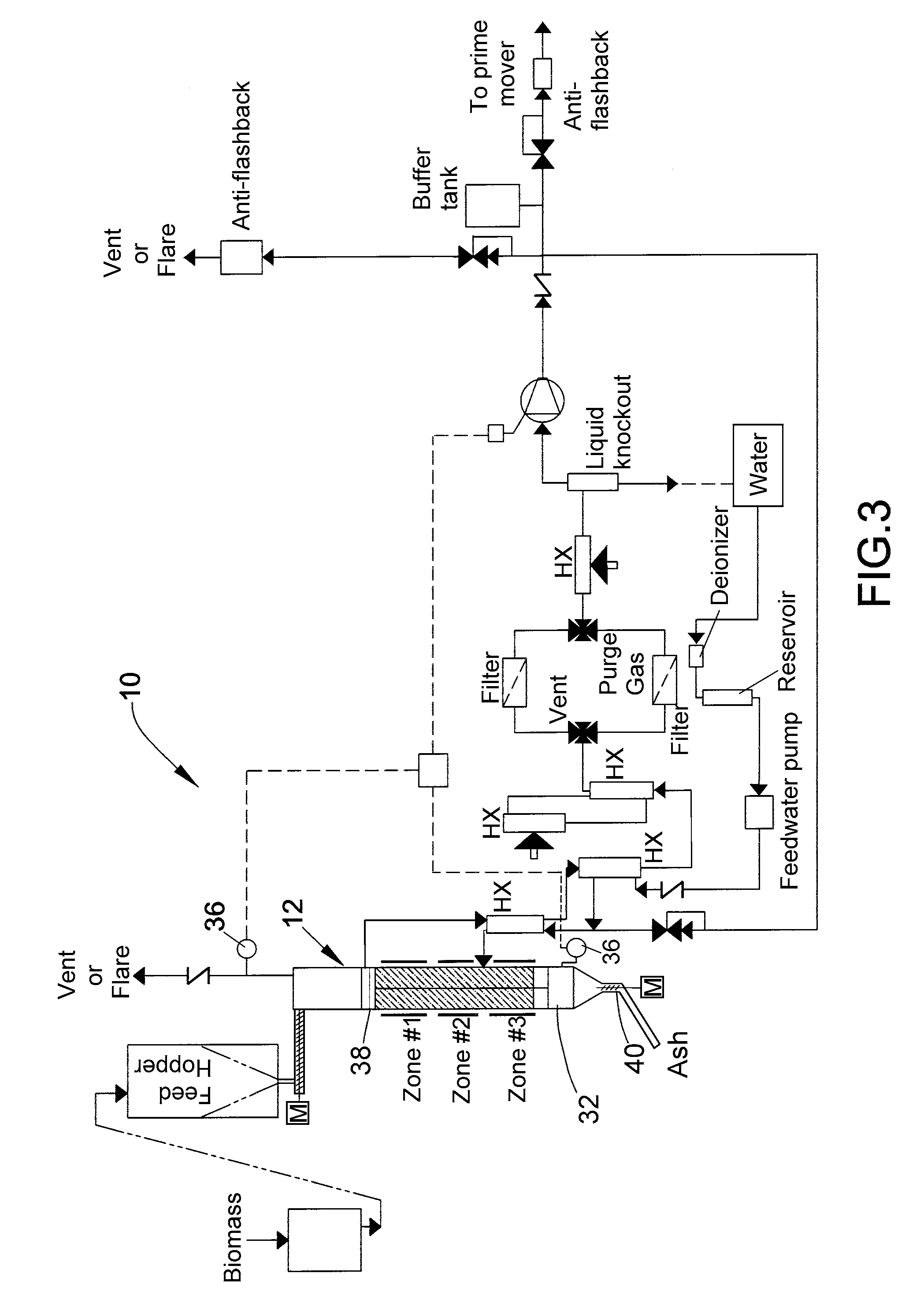
[0017]FIGS. 1 and 2 represent basic concepts relating to a scalable biomass gasifier system in accordance with preferred aspects of the invention. FIG. 1 represents four parallel reactor tubes 12 of a scalable biomass gasifier system 10 represented in FIG. 2. The reactor tubes 12 serve as the containment vessel in which the gasification process occurs, producing syngas as a desired product and dry ash as a byproduct. In FIGS. 1 and 2 further represent the tubes 12 configured in an array (linear, planar, or convex surface), into which biomass particles (not shown) are delivered from a bulk hopper 14 via any suitable type of feeder device 16, represented in FIG. 2 as an auger though other methods of delivery are also within the scope of the invention, such as through the use of a ram or by gravity feed. The reactor tubes 12 are packed together so that incoming biomass does not enter the interstices 18 between adjacent tubes 12. For example, a deflector 20 is represented in FIG. 2 as b...


PUM

PropertyMeasurementUnit
temperatureaaaaaaaaaa
movementaaaaaaaaaa
energy densityaaaaaaaaaa

Abstract

A system and method capable of efficient production of synthesis gas from biomass materials in a manner which can be scaled to relatively large throughput capacities. the system is operable to compact a loose biomass material and simultaneously introduce the compacted biomass material into entrances of internal passages of multiple parallel reactors, heat the compacted biomass material within the reactors to a temperature at which organic molecules within the compacted biomass material break down to form ash and gases comprising carbon monoxide and hydrogen gases, inhibit combustion of the compacted biomass material when heated within the internal passages of the reactors, conduct the carbon monoxide and hydrogen gases through the reactors in a direction opposite the movement of the compacted biomass through the reactors, and remove the ash from the reactor.

Description

CROSS REFERENCE TO RELATED APPLICATIONS[0001]This application claims the benefit of U.S. Provisional Application No. 61 / 212,624, filed Apr. 14, 2009, and is related to U.S. Provisional Application No. 61 / 129,352, filed Jun. 20, 2008. The contents of these prior patent applications are incorporated herein by reference.STATEMENT REGARDING FEDERALLY SPONSORED RESEARCH[0002]This invention was made with government support under USDA Grant number 68-3A75-7-607. Under 37 CFR §401.14, the Government may have certain rights in the invention.BACKGROUND OF THE INVENTION[0003]The present invention generally relates to the conversion of organic lignocellulosic material (biomass) into a useful gas-phase fuel, and more particularly to a system and method capable of scalable and continuous conversion of biomass materials into useful gas-phase fuels.[0004]Biomass gasification is a well-known process for producing synthesis gas (syngas), which as also known in the art is a gas mixture containing vary...

Claims


Application Information

Patent Timeline
Patent Type & Authority Applications(United States)
IPC IPC(8): C10J3/20C10J3/00
CPCC10J3/007Y02E50/14C10K1/024C10B47/44C10B53/02C10J2300/0916C10J2300/0976C10J2300/1269C10J2300/1276C10J2300/1646C10J2300/1693C10J2300/1853C10J2300/1884C10J2300/1892C10J2200/158C10B57/16C10J3/20Y02E50/10Y02P20/145
Inventor SCHUBERT, PETER J.
Owner INDIANA UNIV RES & TECH CORP
Learn More