Systems and Methods for Cooling Optical Fiber

Active Publication Date: 2011-04-28
CORNING INC
View PDF16 Cites 6 Cited by
  • Summary
  • Abstract
  • Description
  • Claims
  • Application Information

AI Technical Summary

Benefits of technology

[0009]In another embodiment, an optical fiber cooling system includes an optical fiber cooling tube positioned in and substantially coaxial with a cooling fluid supply plenum. The optical fiber cooling tube generally defines an optical fiber pathway through the optical fiber cooling system and includes a plurality of cooling fluid inlets positioned along an axial length of the optical fiber cooling tube. The cooling fluid inlets are configured to direct a flow of cooling fluid across the optical fiber pathway from at least two different directions. At least one cooling fluid vent may be disposed along the axial length of the optical fiber cooling tube between first and second ends of the optical fiber cooling tube. The at least one cooling fluid vent may have a cross sectional area which is larger than a cross sectional area of a cooling fluid inlet. Further, the at least one cooling fluid vent may be operable to exhaust cooling flu

Problems solved by technology

After the optical fiber is drawn from the preform, the bare or uncoated optical fiber may be susceptible to damage from mechanical contact.
Such damage may adversely affect both the mechanical and optical properties of the optical fiber.
However, if the coating is applied to the heated optical fiber (e.g., if the coating is applied to the optical fiber immediately after the optical fiber is drawn from the preform) the elevated temperature of the optica

Method used


Image

  • Systems and Methods for Cooling Optical Fiber
  • Systems and Methods for Cooling Optical Fiber
  • Systems and Methods for Cooling Optical Fiber

Examples


Example

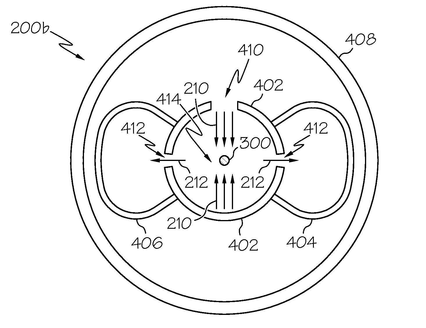
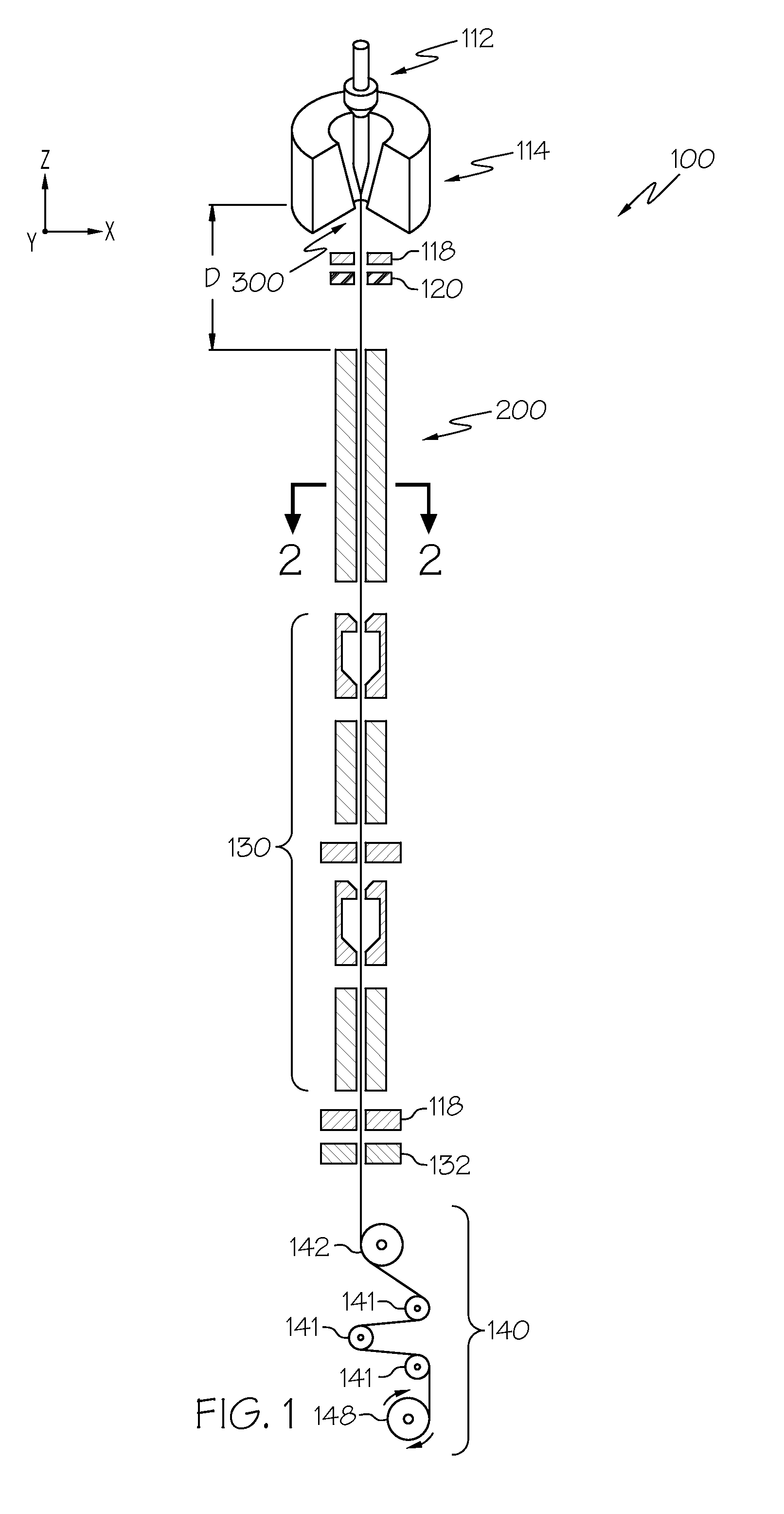
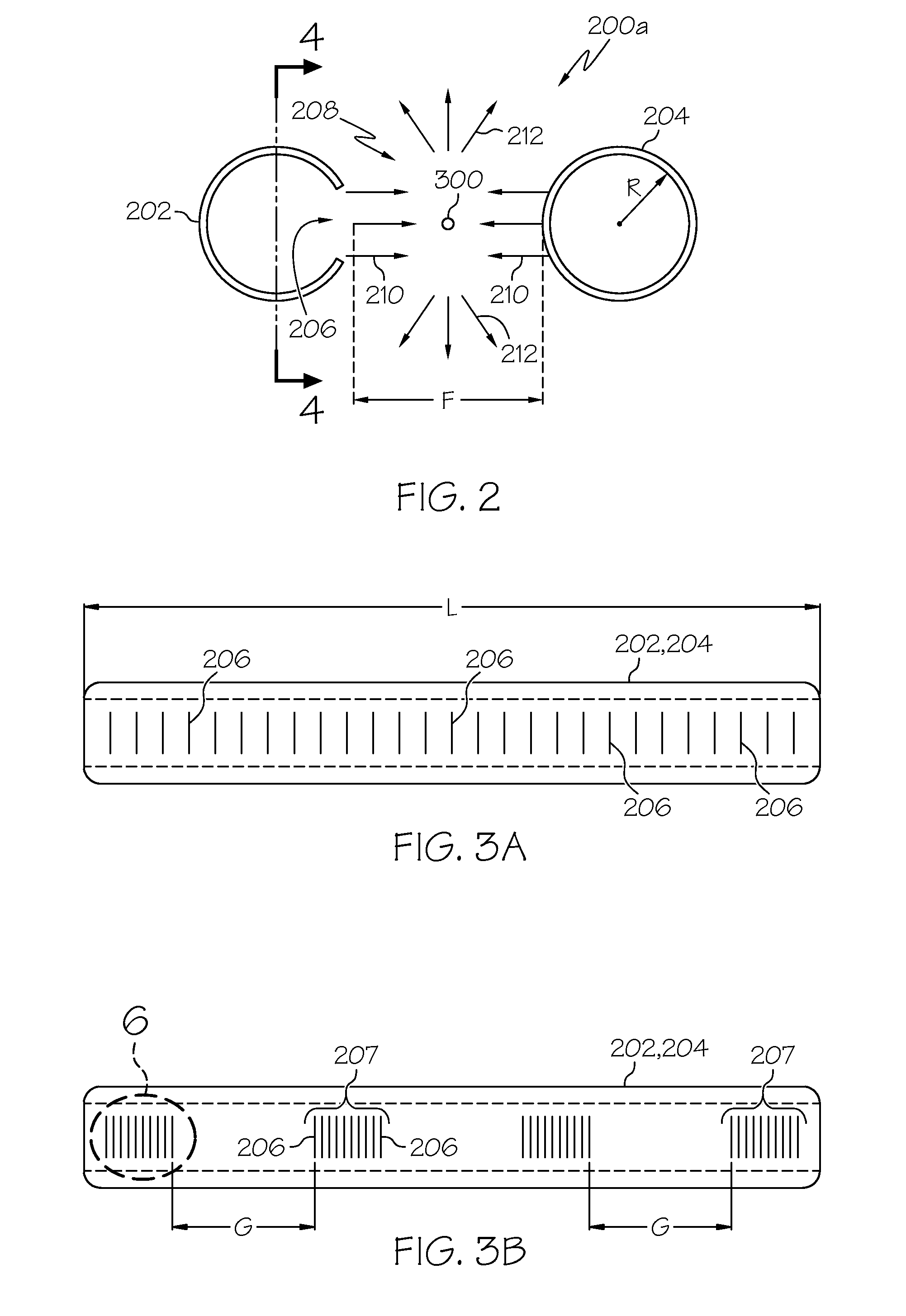
[0024]Reference will now be made in detail to various embodiments of optical fiber cooling systems, examples of which are illustrated in the accompanying drawings. Whenever possible, the same reference numerals will be used throughout the drawings to refer to the same or like parts. One embodiment of an optical fiber cooling system is generally depicted in FIG. 2. The optical fiber cooling system generally comprises a first cooling tube and a second cooling tube oriented in parallel with one another and spaced apart from one another such that an optical fiber pathway is positioned between the first and second cooling tubes. Each of the cooling tubes may comprise a plurality of cooling fluid outlets which are oriented to direct a flow of cooling fluid across the optical fiber pathway towards the opposing cooling tube. Various embodiments of the optical fiber cooling system and systems for drawing optical fiber in which the optical fiber cooling systems are incorporated will be descri...


PUM

PropertyMeasurementUnit
Angleaaaaaaaaaa
Speedaaaaaaaaaa
Widthaaaaaaaaaa

Abstract

In one embodiment, an optical fiber cooling system includes a first cooling tube oriented substantially in parallel with and spaced apart from a second cooling tube such that an optical fiber pathway is positioned between the first cooling tube and the second cooling tube. The first cooling tube includes a plurality of cooling fluid outlets positioned along an axial length of the first cooling tube which are oriented to direct a flow of cooling fluid across the optical fiber pathway towards the second cooling tube. The second cooling tube includes a plurality of cooling fluid outlets positioned along an axial length of the second cooling tube which are oriented to direct a flow of cooling fluid across the optical fiber pathway towards the first cooling tube.

Description

CROSS REFERENCE[0001]The present disclosure claims priority to U.S. Provisional Application 61 / 255,527, filed Oct. 28, 2009 and entitled “Systems and Methods for Cooling Optical Fiber”.BACKGROUND[0002]1. Field[0003]The present specification generally relates to systems and methods for producing optical fiber and, more specifically, to systems and methods for cooling optical fiber.[0004]2. Technical Background[0005]Glass optical fiber is generally formed by drawing the optical fiber from a preform which is heated to a draw temperature in a draw furnace. After the optical fiber is drawn from the preform, the bare or uncoated optical fiber may be susceptible to damage from mechanical contact. Such damage may adversely affect both the mechanical and optical properties of the optical fiber. Accordingly, to prevent such damage, a coating may be applied to the optical fiber soon after the optical fiber is drawn from the preform. However, if the coating is applied to the heated optical fibe...

Claims


Application Information

Patent Timeline
IPC IPC(8): F28D7/10B23P15/26
CPCC03B37/02718C03B37/10Y10T29/49391
Inventor CUMMINGS, GARY ALANKHANNA, SAMIRNEILSON, DOUGLAS GREGGPEDERSEN, THOMAS A.RAHIMINEJAD, MASSOUDREDING, BRUCE WARREN
Owner CORNING INC
Why Eureka
Try Eureka