System for reduced peak power consumption by a cooking appliance

a technology for cooking appliances and peak power consumption, applied in baking ovens, lighting and heating appliances, furnaces, etc., can solve the problems of reducing the peak and average power consumed by the appliance, no active control, and high cost for utility companies, so as to reduce the peak power consumption of the cooking applian

Active Publication Date: 2011-04-28
HAIER US APPLIANCE SOLUTIONS INC
View PDF99 Cites 58 Cited by
  • Summary
  • Abstract
  • Description
  • Claims
  • Application Information

AI Technical Summary

Benefits of technology

[0008]According to one aspect of the present disclosure, a system for reducing peak power consumption in an electromechanically controlled cooking appliance is provided. The system comprises a surface heating unit comprising at least one duty cycle controlled surface heating element, a temperature controlled oven heating element, a controller configured to receive and process utility state signals indicative of the operating state of an associated utility, and a switch responsive to the controller, switchable between a first state and a second state for selectively coupling the oven heating element to a first relatively high voltage power supply and a second relatively low voltage power supply respectively. The controller is configured to switch the switch to the first and second states as a function of the utility state signal.
[0009]According to another aspect of the present disclosure, a power sharing method for reducing peak power consumption of a cooking appliance is provided. The cooking appliance includes at least one duty cycle controlled surface heating element and at least one oven heating element, wherein the at least one oven heating element is energized by a conventional 240 volt ac power supply. The method comprises receiving and processing utility state signals by a controller, the signals being indicative of the operating state of an associated utility, associating the at least one oven heating element to a demand response switch switchable between a first state and a second state, and switching the demand response switch between the first and second state to selectively couple the at least one oven heating element to a first relatively high voltage power supply and a second relatively low voltage power supply respectively.
[0010]According to yet another embodiment of the present disclosure, a power sharing system for reducing peak power consumption of a cooking appliance during an energy savings mode is provided. The system comprises a surface heating unit comprising at least one surface heating element operative according to a duty cycle, an oven cavity, having one or more oven heating elements, a controller configured to receive and process a signal indicative of a current utility state of an associated utility and operative to implement an energy saving mode in response to a signal indicative of a high demand state, a demand response switch arrangement responsive to the controller and to the operating state of the surface heating unit. The demand response switch arrangement is operative in the energy saving mode to enable energization of the oven element by a first relatively high voltage supply when the surface unit is not energized and to enable energization of the oven element by a second relatively low voltage supply when the surface heating unit is energized.

Problems solved by technology

Currently utilities charge a flat rate, but with increasing cost of fuel prices and high energy usage at certain parts of the day, utilities have to buy more energy to supply customers during peak demand.
Utility companies have to find ways to temporarily provide for this higher energy use, which comes at great expense to utility companies.
However, there is no active control beyond the mere on / off switching.
At low settings, reducing power can result in undercooked food and since surface cooking is attended, the consumer can merely increase the power.
This reduces the peak and average power consumed by the appliance.

Method used


Image

  • System for reduced peak power consumption by a cooking appliance
  • System for reduced peak power consumption by a cooking appliance
  • System for reduced peak power consumption by a cooking appliance

Examples


Embodiment Construction

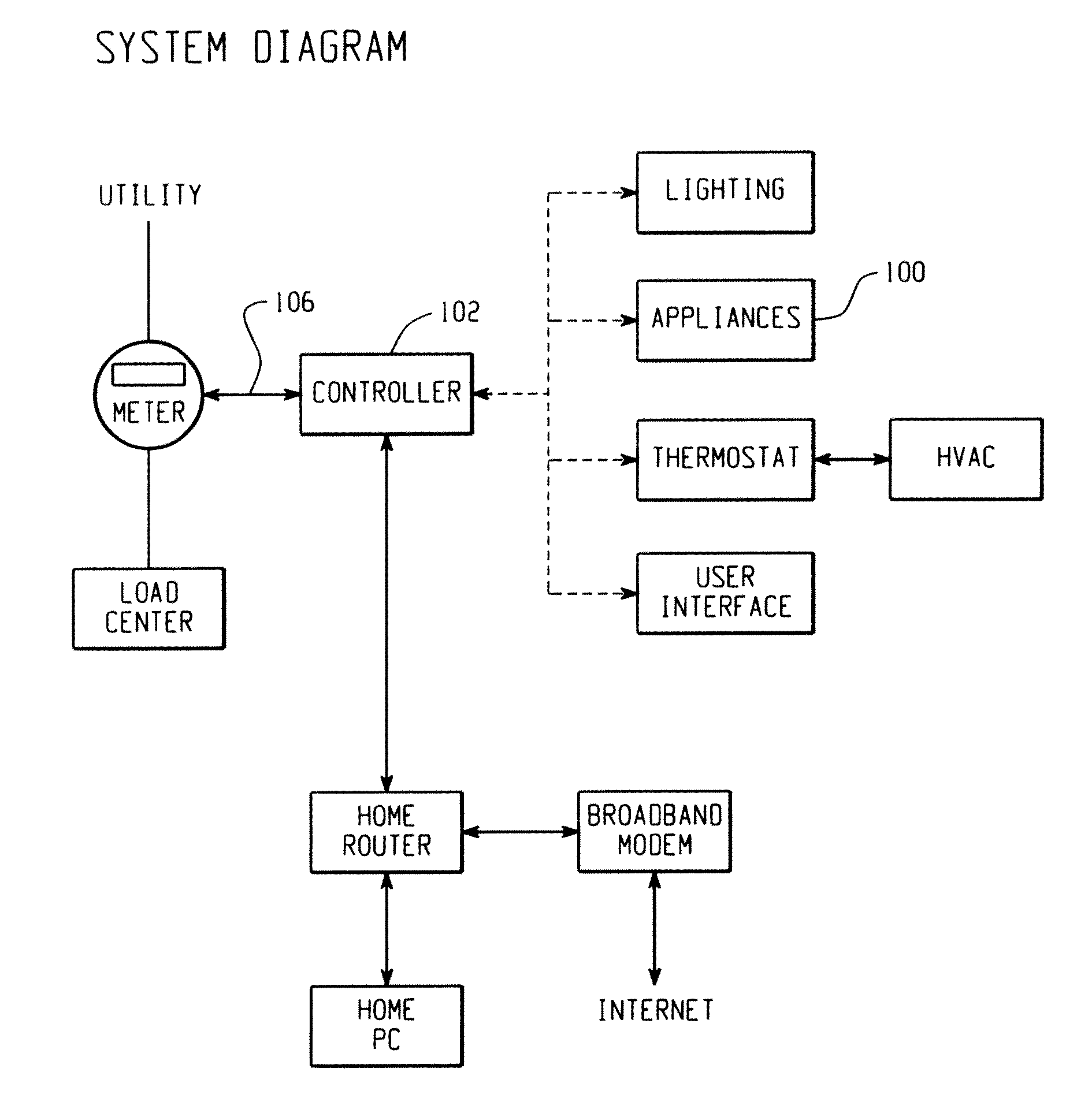
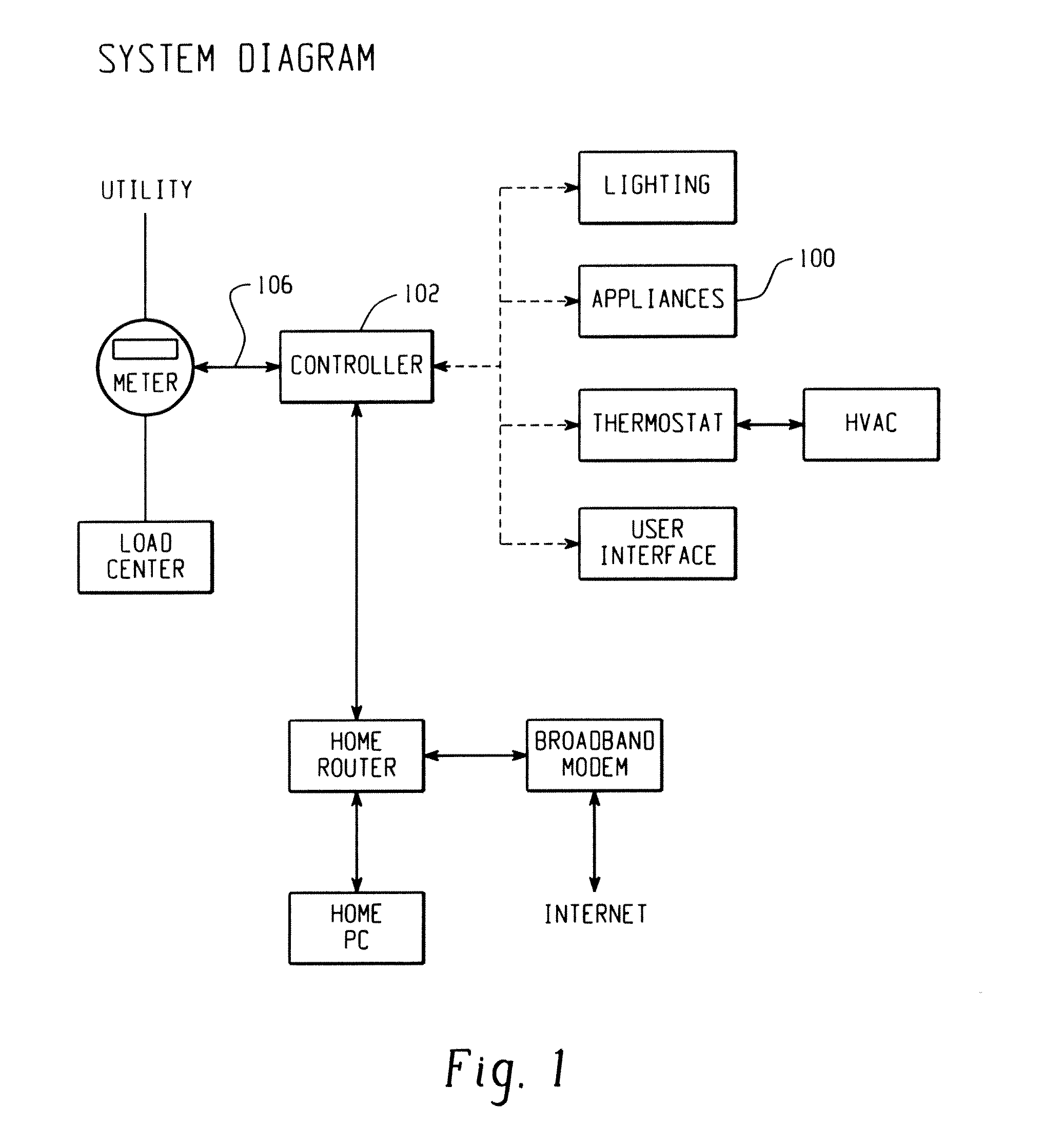
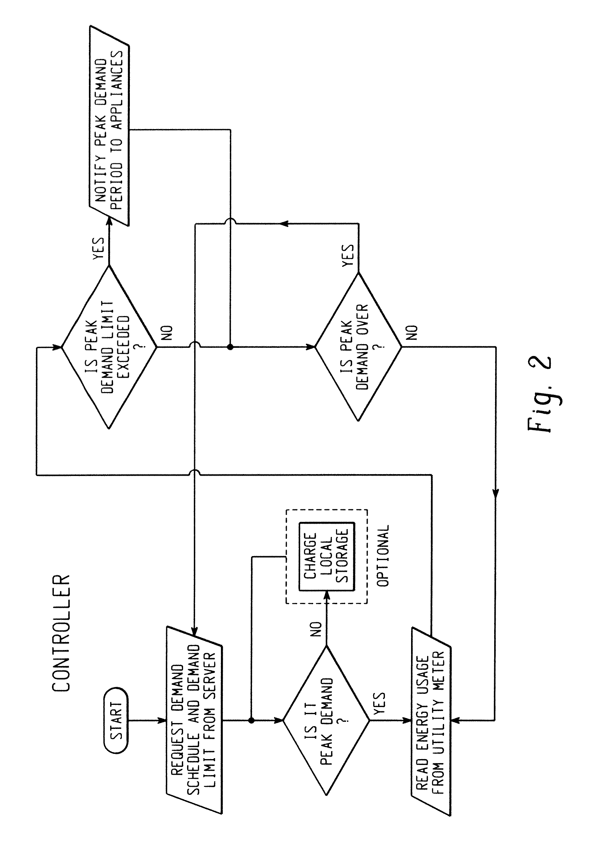
[0022]An exemplary embodiment of an energy management system for household appliances is illustrated in FIG. 1. An electronic controller is provided for communicating with a utility meter and reducing power consumption in response to a peak demand period. A utility meter can also provide the controller the occurrence of peak demand and demand limit. The demand limit can also be set by the home owner. Additionally, the homeowner can choose to force various modes in the appliance control based on the rate the utility is charging at different times of the day. The controller will look at the energy consumption currently used by the home via the utility meter and see if the home is exceeding the demand limit read from the server. If the demand limit is exceeded, the controller will notify the intelligent appliances, lighting and thermostat / HVAC (FIG. 2).

[0023]The interaction between controller and appliances can occur in various ways. For example, in one scenario during a peak demand pe...


PUM


Abstract

According to one aspect of the present disclosure, a system for reducing peak power consumption in an electromechanically controlled cooking appliance is provided. The system comprises a surface heating unit comprising at least one duty cycle controlled surface heating element, a temperature controlled oven heating element, a controller configured to receive and process utility state signals indicative of the operating state of an associated utility, and a switch responsive to the controller, switchable between a first state and a second state for selectively coupling the oven heating element to a first relatively high voltage power supply and a second relatively low voltage power supply respectively. The controller is configured to switch the switch to the first and second states as a function of the utility state signal.

Description

CROSS REFERENCE TO RELATED APPLICATIONS[0001]The present application is a continuation-in-part of U.S. application Ser. No. 12 / 559,597, filed Sep. 15, 2009, which claims priority from U.S. Provisional Patent Application Ser. No. 61 / 097,082 filed 15 Sep. 2008; both of which are expressly incorporated herein by reference, in their entireties.BACKGROUND OF THE DISCLOSURE[0002]This disclosure relates to energy management, and more particularly to energy management of household consumer appliances. The disclosure finds particular application to cooking appliances and is particularly advantageously applied to such appliances with surface heating units and oven heating elements.[0003]Currently utilities charge a flat rate, but with increasing cost of fuel prices and high energy usage at certain parts of the day, utilities have to buy more energy to supply customers during peak demand. Utility companies have to find ways to temporarily provide for this higher energy use, which comes at grea...

Claims


Application Information

Patent Timeline
Patent Type & Authority Applications(United States)
IPC IPC(8): H05B1/02
CPCH02J3/14H02J2310/14
Inventor STEURER, BRIAN M.
Owner HAIER US APPLIANCE SOLUTIONS INC
Why Eureka
Try Eureka