Laminar flow wing optimized for supersonic cruise aircraft

a supersonic cruise aircraft and flow wing technology, applied in the direction of aircrafts, wing shapes, transportation and packaging, etc., can solve the problems of limited thickness-chord ratios (t/c) and wave drag appreciably, and achieve the effect of improving computational optimization techniques and variation over the span

Active Publication Date: 2011-04-28
AERION INTPROP MANAGEMENT CORP
View PDF7 Cites 32 Cited by
  • Summary
  • Abstract
  • Description
  • Claims
  • Application Information

AI Technical Summary

Benefits of technology

[0014]The shaping of the portion of the wing in the zone of fuselage influence, and contouring the fuselage itself in the vicinity of the wing, are critical to the overall performance and design optimization in accordance with two primary considerations. The first is reduction of volume wave drag of the combined wing-fuselage system, while the second is reduction of skin friction drag on the wing by increasing its extent of laminar flow. The latter is a function of the pressure distribution on the wing, which depends upon both the local airfoil shapes and the fuselage shape adjacent to and forward of the wing in supersonic flight. The pressure gradients on the wing outboard of the fuselage zone can either facilitate NLF on the wing surface or suppress it, depending on whether such pressure gradients are respectively “favorable”, “adverse” or “crossflow”, as such terms are understood in the art. The object of the design optimization is to develop wing shapes in combination with fuselage shapes which minimize the sum of wave drag plus skin friction drag, noting that the skin friction drag of the wing depends on the amount of its surface characterized by low drag laminar flow. The remainder of the wing, as well as most of the fuselage, has higher skin friction drag, associated with turbulent flow. For an aircraft whose design goal is maximum range, this shaping is done for several selected wing thickness distributions along the span, each such thickness distribution having a corresponding wing weight, so that the overall design optimum can be determined taking into account both drag and weight in determining the aircraft range. It is well understood in the art that increasing empty weight for a given aircraft gross takeoff weight offsets fuel weight and thereby reduces range.

Problems solved by technology

In our previous design studies, the wing was limited to thickness-chord ratios (t / c) for which the volume wave drag was appreciably less than the drag savings resulting from laminar skin friction vs turbulent skin friction.

Method used


Image

  • Laminar flow wing optimized for supersonic cruise aircraft
  • Laminar flow wing optimized for supersonic cruise aircraft
  • Laminar flow wing optimized for supersonic cruise aircraft

Examples


Embodiment Construction

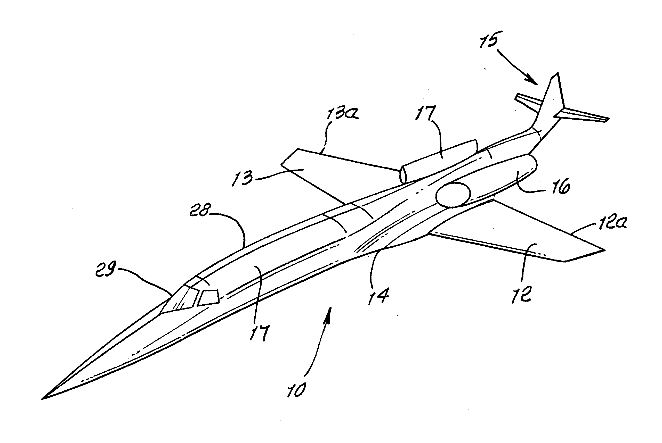
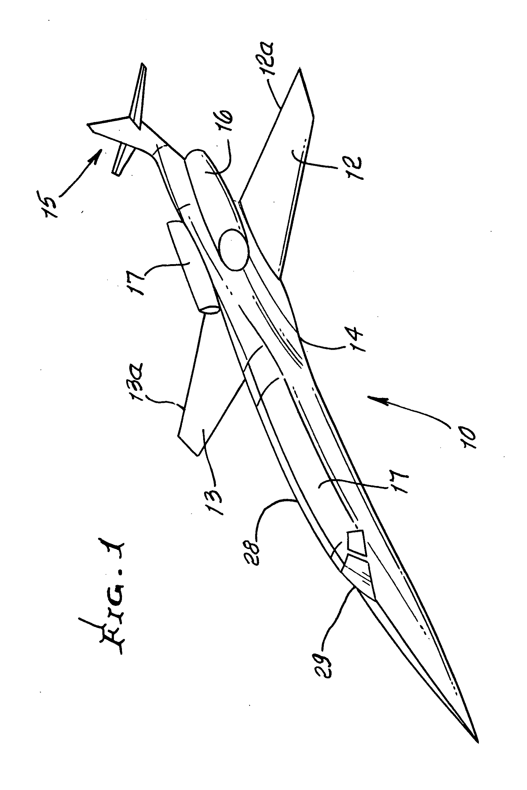
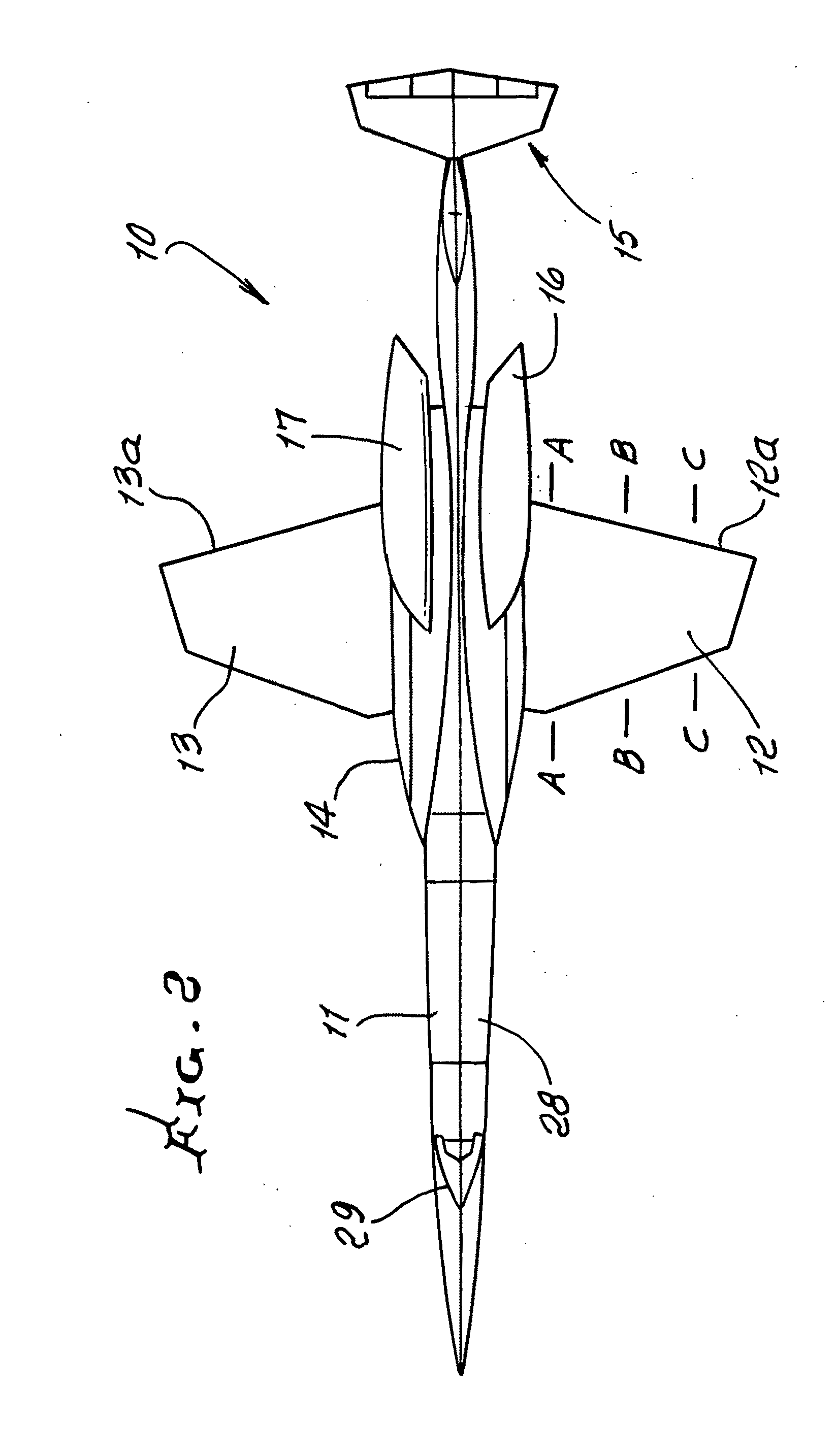
[0026]In FIGS. 1 and 2, the supersonic aircraft 10, has a fuselage 11, wings 12 and 13, strake 14, and tail 15. Two engine nacelles 16 and 17 are located at opposite sides of the fuselage, and project rearwardly of the wing trailing edges 12a and 13a. A cabin and cockpit are shown at 28 and 29, respectively.

[0027]FIGS. 3a, 3b and 3c show wing biconvex surfaces 130 and 131, along the span. See also airfoil chord C and thickness dimension t as follows:

[0028]CA and tA, at A-A

[0029]CB and tB, at B-B

[0030]CC and tC, at C-C

[0031]FIG. 4 shows the wing-fuselage intersection region, in which the trailing edge line 13a intersection with the fuselage center line 30 is indicated at 31; and the wing has a leading edge 18, with projected edge line 18a intersection with the fuselage center line indicated at 19. Mach lines 20 and 21 projected from 19 and 31 respectively intersect at 22. A chord line 23 intersects 22, as shown. The wing extent 24 outboard of chord line 23 is considered to be outboar...


PUM


Abstract

A method of providing an aircraft having a fuselage and a wing configured for extensive laminar flow at design cruise conditions, the method characterized by a) providing wing biconvex-type airfoils having values of thickness, chord and shape along the wing span which provide substantially optimal aircraft range at design cruise conditions, considering the influences of wing drag and wing weight; b) providing wing leading edges, which are configured to effect laminar flow; c) providing fuselage and wing contours which, in combination, produce reduced total wave drag and produce extensive areas of laminar boundary layer flow on the wing; and d) providing wing sweep angularity that facilitates provision of a), b) and c).

Description

BACKGROUND OF THE INVENTION[0001]This invention relates generally to the design configuration of supersonic aircraft with wings designed for extensive natural laminar flow (NLF), and more particularly to optimization of wing thickness and fuselage cross section relationship criteria, for such supersonic aircraft.[0002]Supersonic natural laminar flow wing configurations are desirable for efficient supersonic cruise. Principal features are low sweep, sharp (actually very thin) leading edge, and thin biconvex-type airfoils offering a supersonic cruise drag advantage as a result of reduced skin friction drag associated with NLF, which more than offsets increased drag due to thickness (volume wave drag). The importance of laminar boundary layer (BL) flow in terms of drag reduction can be seen from the fact that for typical supersonic cruise flight conditions the laminar skin friction drag is approximately a factor of ten less than turbulent skin friction drag associated with traditional ...

Claims


Application Information

Patent Timeline
Patent Type & Authority Applications(United States)
IPC IPC(8): B64C3/14B64C3/16B64C30/00
CPCB64C3/10Y02T50/12B64C30/00B64C3/14Y02T50/10
Inventor TRACY, RICHARD R.STURDZA, PETERCHASE, JAMES D.
Owner AERION INTPROP MANAGEMENT CORP
Why Eureka
Try Eureka