
Mobile terminal and charge current setting method thereof

a mobile terminal and current setting technology, applied in battery data exchange, power supply for data processing, transportation and packaging, etc., can solve the problems of increasing the battery capacity, increasing the charge time disadvantageously, and increasing the difference between ta using 1a and ta using 700 ma, so as to prevent mis-operation of the mobile terminal during charging and effectively discriminate a type of charger

Inactive Publication Date: 2011-04-28
LG ELECTRONICS INC
View PDF19 Cites 59 Cited by
  • Summary
  • Abstract
  • Description
  • Claims
  • Application Information

AI Technical Summary

Benefits of technology

The present invention provides a mobile terminal and method for setting a charge current by discriminating the type of charger. The mobile terminal includes a receptacle for inserting a charger and a controller for identifying the type of charger based on the data pins of the charger and the receptacle. The controller then sets the charge current based on the type of charger. This allows the mobile terminal to accurately set the charge current by identifying the type of charger, prevent mis-operation of the mobile terminal during charging, and ensure the proper charging of the mobile terminal.

Problems solved by technology

However, the recent tendency to use smart phones increases the battery capacity.
Accordingly, when a mobile terminal having an increased battery capacity is charged by use of the TA, charge time disadvantageously increases as long as the increased battery capacity.
In this case, distinguishing TA using 1A from TA using 700 mA rises as an important problem.
Here, since the ID pin is included in the USB cable other than TA, if TA header is switched, there is no way to identify the TA head.
Consequently, if a mobile terminal, which is charged with 1A, uses the existing TA using 700 mA, since the mobile terminal tries to maintain its charge current at 1A, an overload occurs at TA, which causes an over current protection at TA, resulting in damage on TA.

Method used


Image

  • Mobile terminal and charge current setting method thereof
  • Mobile terminal and charge current setting method thereof
  • Mobile terminal and charge current setting method thereof

Examples


Embodiment Construction

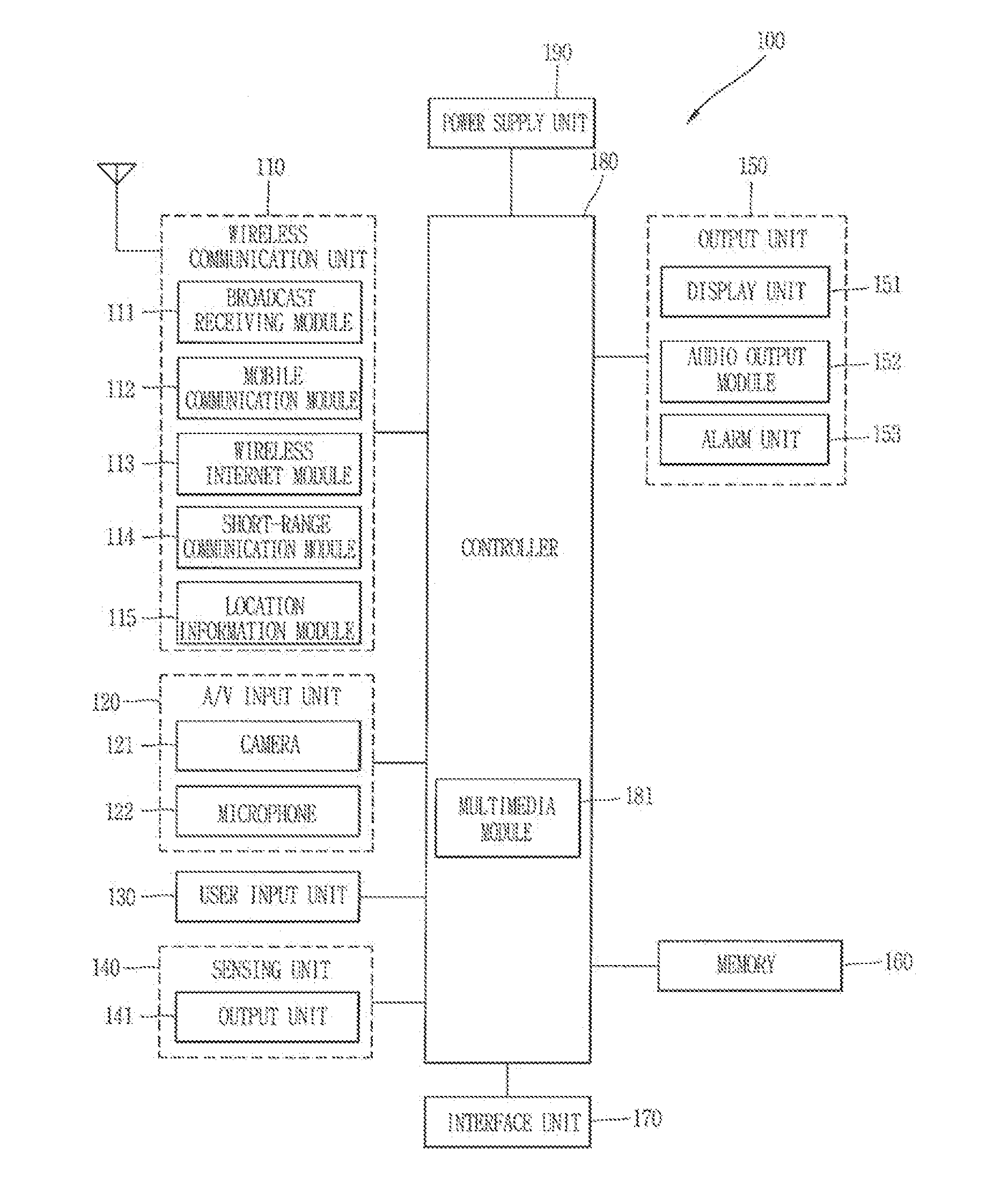
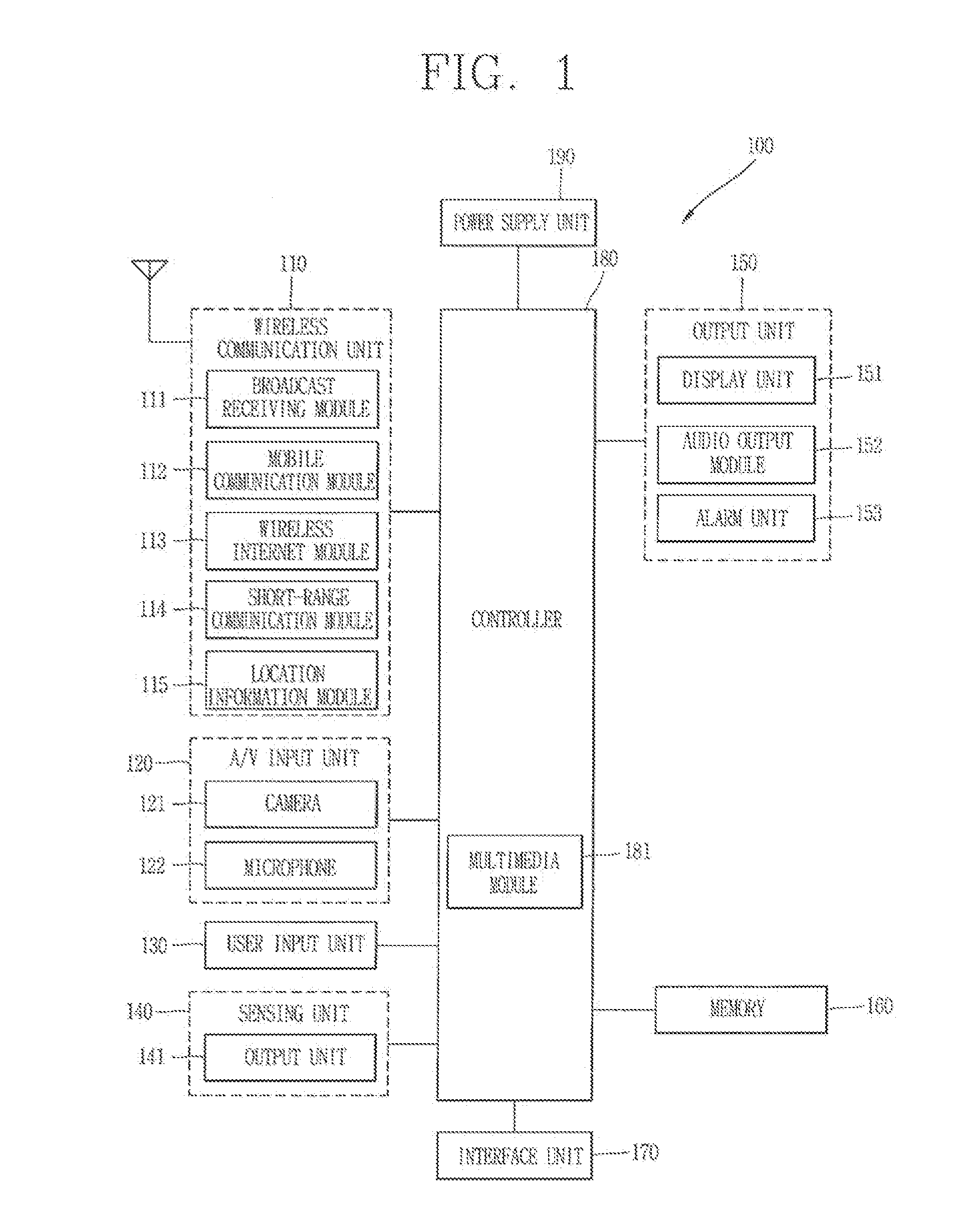
[0049]Description will now be given in detail of preferred configurations of mobile terminals according to the present invention, with reference to the accompanying drawings. Hereinafter, suffixes “module” and “unit or portion” for components used herein in description are merely provided only for facilitation of preparing this specification, and thus they are not granted a specific meaning or function. Hence, it should be noticed that “module” and “unit or portion” can be used together.

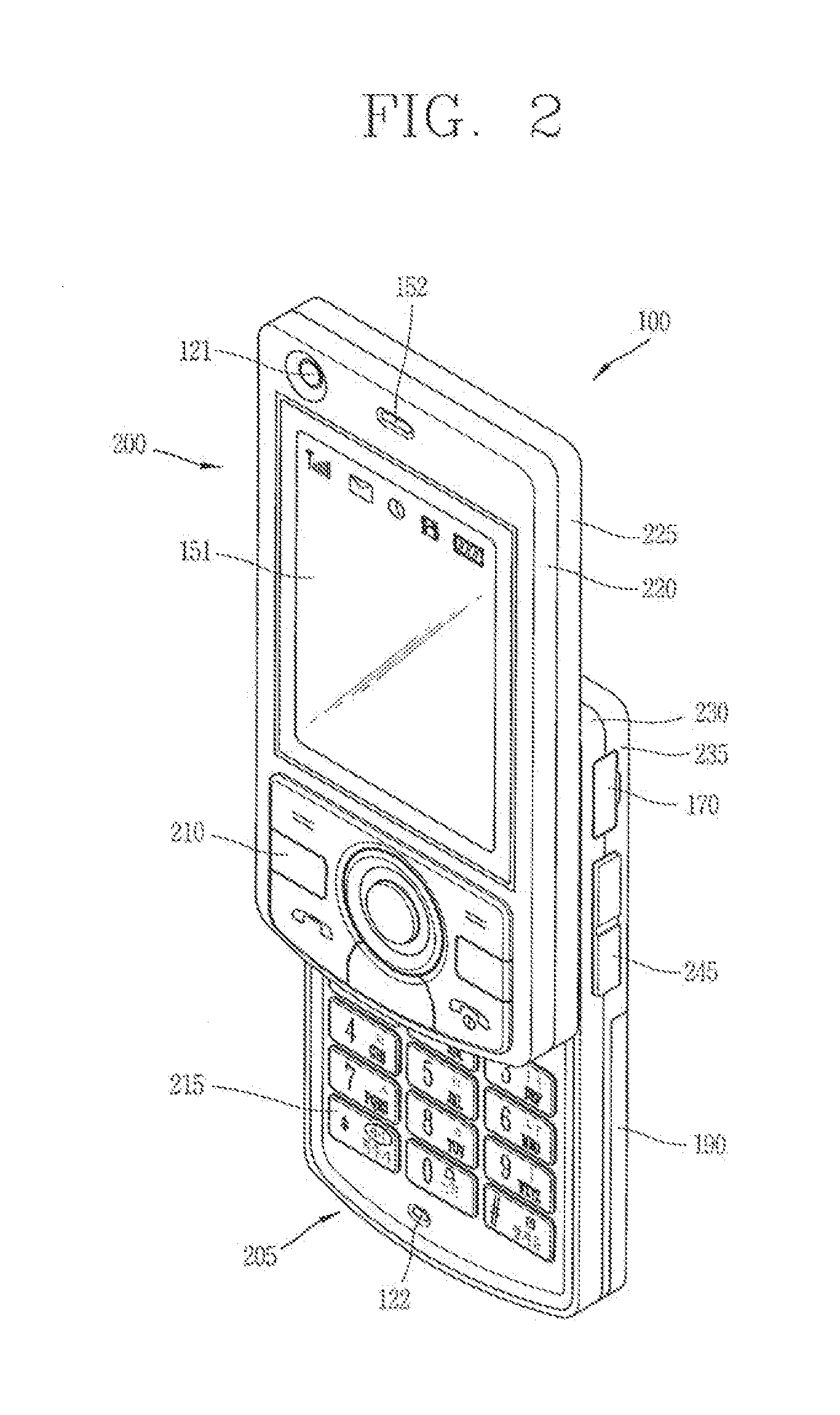
[0050]Mobile terminals may be implemented using a variety of different types of terminals. Examples of such terminals include mobile terminals, such as mobile phones, smart phones, notebook computers, digital broadcast terminals, Personal Digital Assistants (PDA), Portable Multimedia Players (PMP), navigators and the like, and stationary terminals, such as digital TVs, desktop computers and the like. The following description assumes that the terminal is a mobile terminal. However, it can be easily u...


PUM


Abstract

Disclosed are a mobile terminal capable of effectively discriminating a mobile terminal charger so as to set an appropriate charge current, and a method for charging a charge current thereof. To this end, when a charger (e.g., Travel Adaptor (TA)) is inserted via a cable, a short-circuited state of a data pin of the charger is checked such that a route is switched to form a closed loop defined by data pins and provided with predetermined power when the data pin of the charger is in the short-circuited state, and the voltage applied to the formed closed loop is compared with a predetermined reference value, thereby determining a type of the charger. Therefore, when various types of chargers are inserted in the mobile terminal via a cable, the corresponding type of charger is determined so as to set an appropriate charge current, resulting in ensuring a fast charging operation and minimizing damage on the charger.

Description

CROSS-REFERENCE TO RELATED APPLICATION[0001]Pursuant to 35 U.S.C. §119(a), this application claims the benefit of earlier filing date and right of priority to Korean Application No. 10-2009-0100881, filed on Oct. 22, 2009, the contents of which is incorporated by reference herein in its entirety.BACKGROUND OF THE INVENTION[0002]1. Field of the Invention[0003]The present invention relates to charging of a mobile terminal, and particularly, to a mobile terminal[0004]2. Background of the Invention[0005]Mobile terminals may be configured to perform various functions, for example, data and voice communication, capturing images or video, storing voice, reproducing music files via a speaker system, displaying images or video and the like. Some of mobile terminals may include an additional function of playing games, and other mobile terminals may be implemented as multimedia players. In addition, in recent time, mobile terminals can receive broadcast or multicast signals to allow viewing of...

Claims


Application Information

Patent Timeline
Patent Type & Authority Applications(United States)
IPC IPC(8): H02J7/00
CPCH02J7/0042G06F1/26H02J7/0055H02J2007/0062H02J7/00045H02J2207/40H04B1/40H02J7/00
Inventor CHANG, SEOCKJUN
Owner LG ELECTRONICS INC
Learn More