Capacitive touch display panel

Inactive Publication Date: 2011-04-28
CHUNGHWA PICTURE TUBES LTD
View PDF2 Cites 32 Cited by
  • Summary
  • Abstract
  • Description
  • Claims
  • Application Information

AI Technical Summary

Benefits of technology

[0009]The capacitive touch display panel of the present invention includes the transparent conductive sensor pads and the non-transparent conductive patterns. The electrical conductivity of the non-transparent conductive patterns is higher than that of the transparent conductive sens

Problems solved by technology

However, it is difficult for large-sized touch display panels to identify the input signals correct

Method used


Image

  • Capacitive touch display panel
  • Capacitive touch display panel
  • Capacitive touch display panel

Examples


Example

[0014]Certain terms are applied throughout the following description and claims to refer to particular components. As those of ordinary skill will appreciate, manufacturers may refer to a component by different names. This document does not intend to distinguish between components that differ in name but in function. In the following discussion and in the claims, the terms “include”, “including”, “comprise”, and “comprising” are used in an open-ended fashion, and thus should be interpreted to mean “including, but not limited to . . . ”.

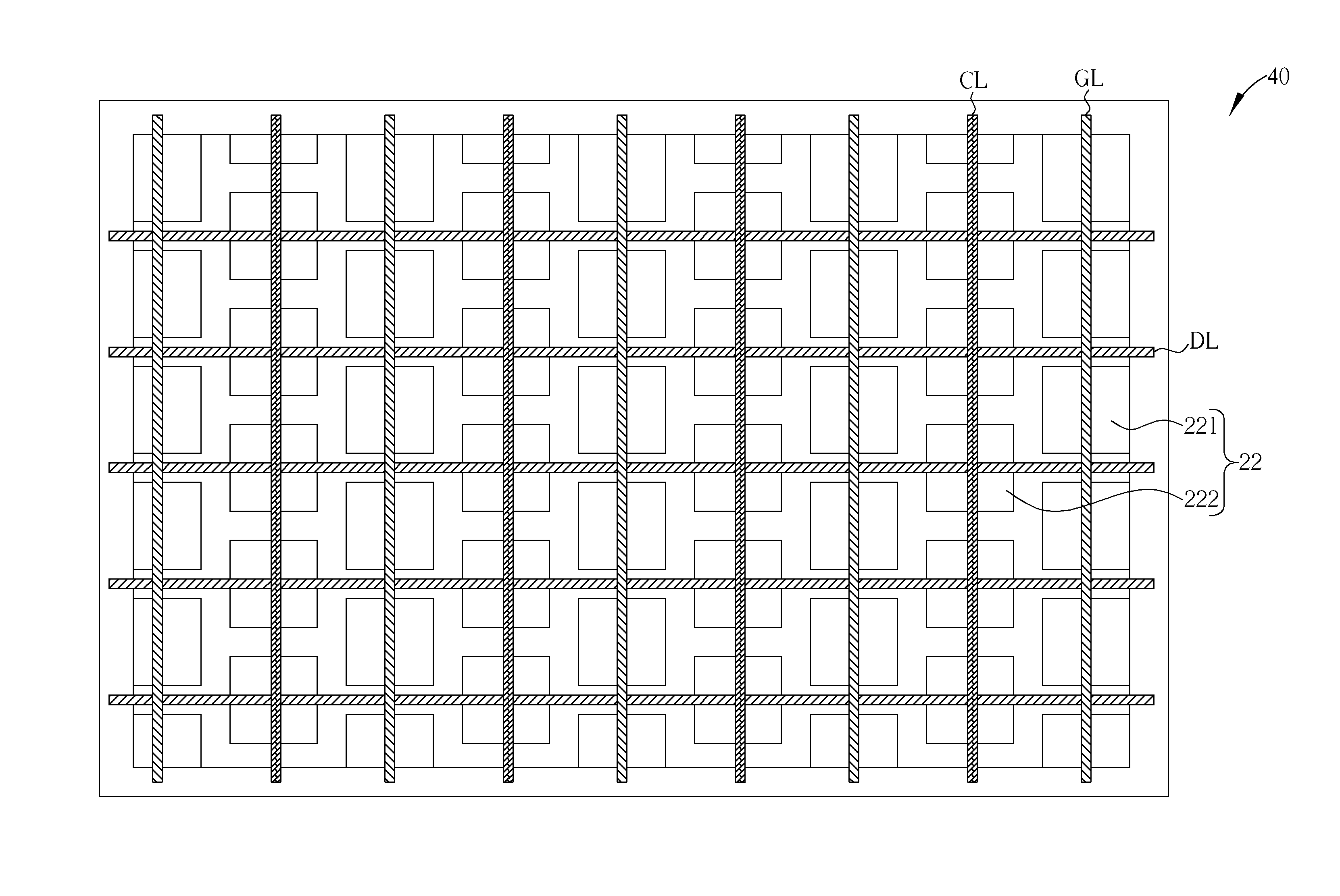
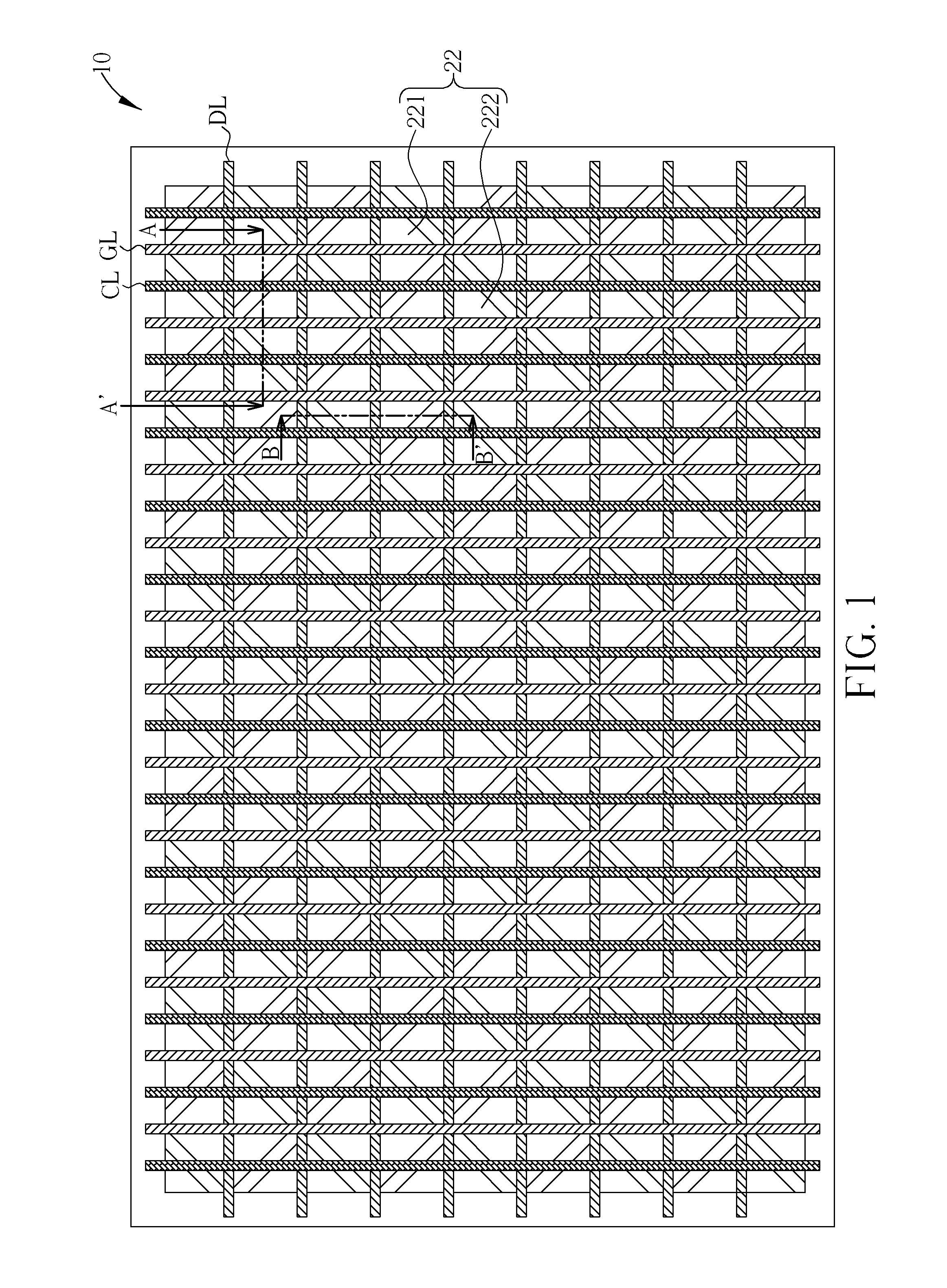
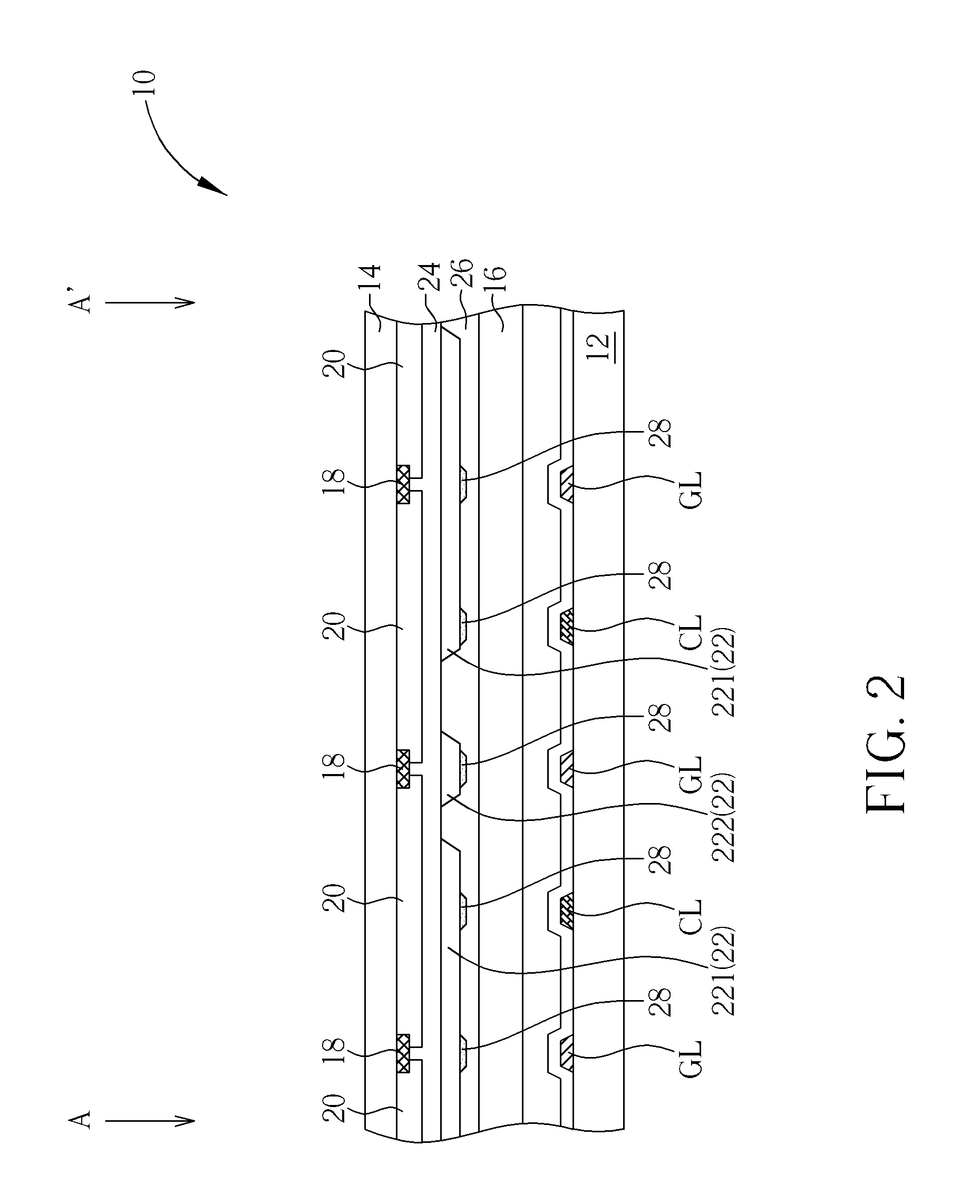
[0015]FIGS. 1 to 3 are schematic diagrams showing a capacitive touch display panel according to a preferred embodiment of the present invention. FIG. 1 is a bottom-view, FIG. 2 is a cross-sectional view along A to A′ of FIG. 1, and FIG. 3 is a cross-sectional view along B to B′ of FIG. 1. In order to highlight the characteristics of the present invention, some components are not shown in FIG. 1. As shown in FIGS. 1 to 3, a capacitive touch display pan...


PUM


Abstract

A capacitive touch display panel includes a first substrate, a second substrate, an opaque pattern, a plurality of transparent conductive sensor pads, and a plurality of non-transparent conductive patterns. The first substrate and the second substrate are disposed oppositely. The transparent conductive sensor pads are disposed on the second substrate. The non-transparent conductive patterns are disposed on the second substrate, and the non-transparent conductive patterns and the transparent conductive sensor pads are electrically connected and overlapping. The conductivity of the non-transparent conductive patterns is higher than that of the transparent conductive sensor pads, and the non-transparent conductive patterns are corresponding to the opaque pattern.

Description

BACKGROUND OF THE INVENTION[0001]1. Field of the Invention[0002]The present invention relates to a capacitive touch display panel, and more particularly, to a capacitive touch display panel with low impedance and high aperture ratio.[0003]2. Description of the Prior Art[0004]In the current market of diverse consumer electronics, touch panels are broadly applied as communications interfaces between human and machine in the portable information products such as mobile phones, Global Positioning System (GPS), and digital video / audio players. Since the consumer electronics tend to be thinner and more light-weighted, traditional input equipments including keyboard and mouse, which take more space, are gradually replaced by touch panels, and touch panels have become one of the key components.[0005]However, it is difficult for large-sized touch display panels to identify the input signals correctly, which results from a high impedance of the sensor pads made of transparent conductive mater...

Claims


Application Information

Patent Timeline
IPC IPC(8): G06F3/045
CPCG06F3/044G02F1/13338G02F1/133514G06F3/0443
Inventor LI, LINGCHEN, YING-HUILIU, CHIA-LIN
Owner CHUNGHWA PICTURE TUBES LTD
Why Eureka
Try Eureka