
Method and System for Wafer Inspection

a technology of wafers and inspection methods, applied in the direction of photomechanical treatment, printing, instruments, etc., can solve the problems of large amount of attention needed for devices with dense patterns, insufficient distribution of existing polygons on two separate designs, and creation of new line-ends

Inactive Publication Date: 2011-04-28
INTERUNIVERSITAIR MICRO ELECTRONICS CENT (IMEC VZW) +1
View PDF2 Cites 13 Cited by
  • Summary
  • Abstract
  • Description
  • Claims
  • Application Information

AI Technical Summary

Benefits of technology

[0008]Certain inventive aspects relate to methods and systems for evaluating a multiple patterning lithographic processing and the devices obtained thereby. It is an advantage of embodiments of the present invention that a qualitative and / or quantitative evaluation of a multiple patterning lithographic process and the stitching applied thereby can be obtained. It is an advantage of embodiments according to the present invention that methods and systems are provided allowing process control of a multiple patterning lithographic process. It is an advantage of embodiments of the present invention that methods and systems are provided for detecting weaker points in a pattern through process variations when applying multiple patterning lithographic processing. It is an advantage of embodiments according to the present invention that methods and systems are provided allowing evaluation of each of the patterning steps used during multiple patterning as well as evaluation of stitching points where the different patterns used for multiple patterning are recombined.
[0009]It is an advantage of embodiments according to the present invention that accurate measurement of the critical dimension (CD) and overlay after multiple patterning lithography can be performed to determine whether the recombination or stitching of different patterns / designs / polygons during multiple patterning lithographic processing was done properly and within the needed specifications. It is an advantage of embodiments according to the present invention that these allow distinguishing between different populations of polygons issued from different patterning steps during multiple patterning lithographic processing.
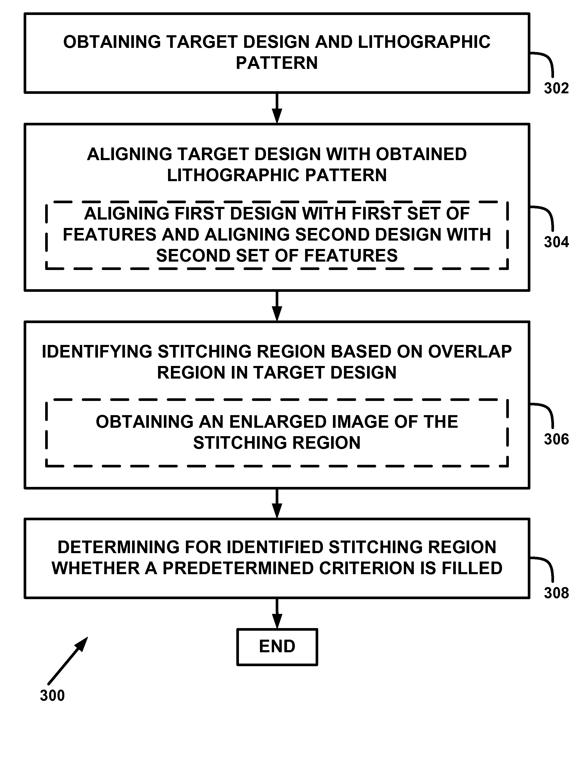
[0010]One inventive aspect relates to a method for evaluating a lithographic pattern, the lithographic pattern being obtained using multiple patterning lithographic processing according to a target design composed of a first design and at least a second design, the method comprising aligning a target design with a lithographic pattern, wherein the target design comprises at least a first design and a second design. The method may further comprise identifying a stitching region in the lithographic pattern, the stitching region being based on a region of overlap of the first design and the second design, and determining for the identified stitching region in the lithographic pattern whether a predetermined criterion is fulfilled. It is an advantage of embodiments according to the present invention that accurate localization of stitching regions in the lithographic processing can be performed, resulting in the possibility for improved characterization and control of stitching in multiple patterning lithographic processing and / or in improved structures thus obtained.

Problems solved by technology

Consequently, a lot of attention is needed for devices with a dense pattern.
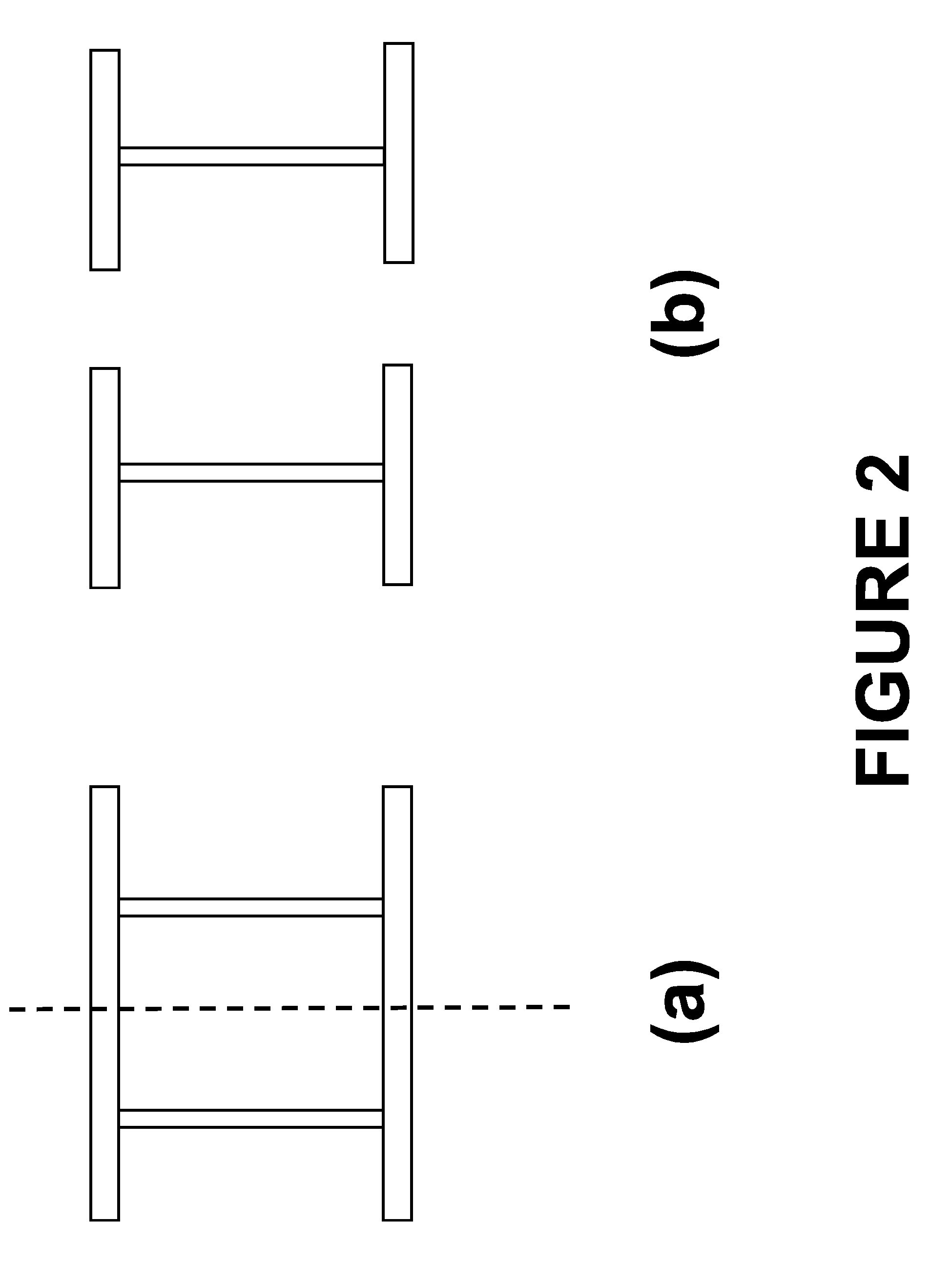
In double patterning of random logic applications with small pitch, distributing existing polygons on two separate designs may not be sufficient.
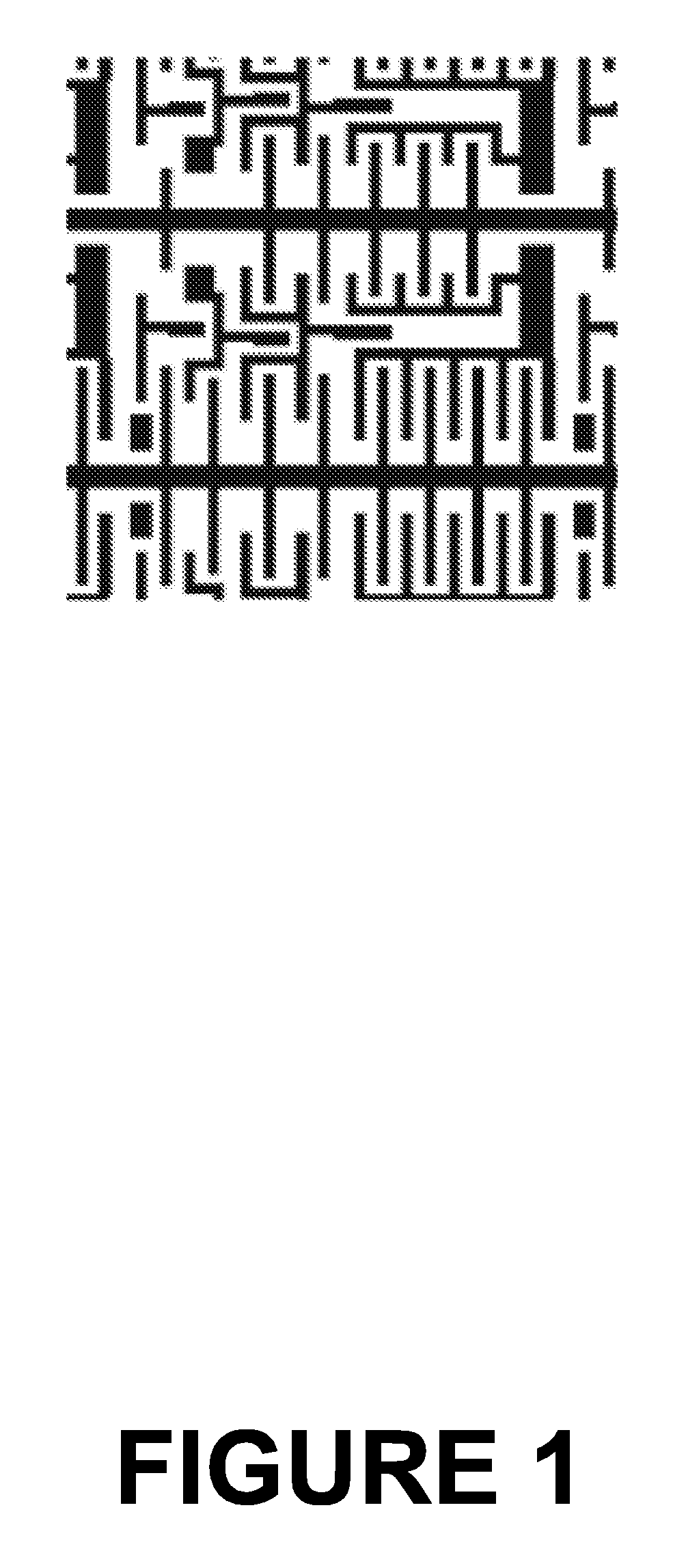
However, this results in the creation of new line-ends that needs to recombine during the double patterning process at so-called stitching points.
In some embodiments, when a local deviation of the edge placement error is larger than the predetermined threshold, the decision may be that necking problems are present due to stitching.

Method used


Image

  • Method and System for Wafer Inspection
  • Method and System for Wafer Inspection
  • Method and System for Wafer Inspection

Examples


Embodiment Construction

[0048]One or more embodiments of the present invention will now be described in detail with reference to the attached figures, though the invention is not limited thereto. The drawings described are only schematic and are non-limiting. In the drawings, the size of some of the elements may be exaggerated and not drawn on scale for illustrative purposes. The dimensions and the relative dimensions do not necessarily correspond to actual reductions to practice of the invention. Those skilled in the art can recognize numerous variations and modifications of this invention that are encompassed by its scope. Accordingly, the description of preferred embodiments should not be deemed to limit the scope of the present invention.

[0049]Furthermore, the terms first, second and the like in the description are used for distinguishing between similar elements and not necessarily for describing a sequential or chronological order. It is to be understood that the terms so used are interchangeable und...


PUM


Abstract

A method and system for evaluating a lithographic pattern obtained using multiple-patterning lithographic processing are presented. In one aspect, the method includes aligning a target design with a lithographic pattern. The target design may comprise a first design and a second design. The method further comprises identifying in the lithographic pattern a stitching region based on a region of overlap between the first design and the second design. The method further comprises determining for the identified stitching region whether a predetermined criterion is fulfilled. In some embodiments, determining whether a predetermined criterion is fulfilled may comprise determining a line or trench minimum width. Alternately or additionally, determining whether a predetermined criterion is fulfilled may comprise determining a stitching metric for the identified stitching region, and evaluating whether or not the stitching metric fulfills the predetermined criterion.

Description

CROSS-REFERENCE TO RELATED APPLICATIONS[0001]This application claims priority to U.S. Provisional Patent Application 61 / 255,664 filed Oct. 28, 2009, the contents of which are incorporated by reference herein in their entirety.FIELD OF THE INVENTION[0002]The present invention relates to the field of lithographic processing of devices, such as in semiconductor processing. More particularly, the present invention relates to methods and systems for evaluating a lithographic pattern obtained using a multiple patterning lithographic process.BACKGROUND OF THE INVENTION[0003]In the production of today's integrated circuits, optical lithography is one of the key manufacturing techniques. In order to cope with the ongoing miniaturization of integrated circuits or other devices and its associated problems, new lithographic techniques need to be introduced. Possibilities used nowadays (45 nm technology node and below) are high numerical aperture solutions such as immersion lithographic processi...

Claims


Application Information

Patent Timeline
IPC IPC(8): G03B27/52
CPCG03F7/70466G03F7/70633G03F7/70616G03F7/70475
Inventor PAUL WIAUX, VINCENT JEAN-MARIE PIERREMATSUOKA, RYOICHIKOSHIHARA, SHUNSUKESAKAI, HIDEO
Owner INTERUNIVERSITAIR MICRO ELECTRONICS CENT (IMEC VZW)
Learn More