Method and apparatus for controlling uplink power in a wireless communication system

a wireless communication system and uplink power technology, applied in the field of wireless communication, can solve the problems of complex and difficult determination of the c/n of each transmission channel, greatly affected ues at the cell edge, and achieve the effect of maintaining the stability of the channel environment and improving the qos of the wireless communication system

Inactive Publication Date: 2011-04-28
LG ELECTRONICS INC
View PDF15 Cites 98 Cited by
  • Summary
  • Abstract
  • Description
  • Claims
  • Application Information

AI Technical Summary

Benefits of technology

The present invention can improve the QoS of a wireless communication system by maintaining the stability of the channel environment of the wireless communication system, while facilitating a UE to determine uplink power in the wireless communication system.
It will be appreciated by persons skilled in the art

Problems solved by technology

Especially UEs at a cell edge are greatly affected by path loss and inter-cell interference in a multi-cell environment.
The problem of the UE's complexity has been brought up from the method for determining a target SINR differently for different modes.
Considering this information offset reflects a resource size that varies with a Modulation and Coding Scheme (MCS) level

Method used


Image

  • Method and apparatus for controlling uplink power in a wireless communication system
  • Method and apparatus for controlling uplink power in a wireless communication system
  • Method and apparatus for controlling uplink power in a wireless communication system

Examples


Embodiment Construction

Reference will now be made in detail to the preferred embodiments of the present invention, examples of which are illustrated in the accompanying drawings.

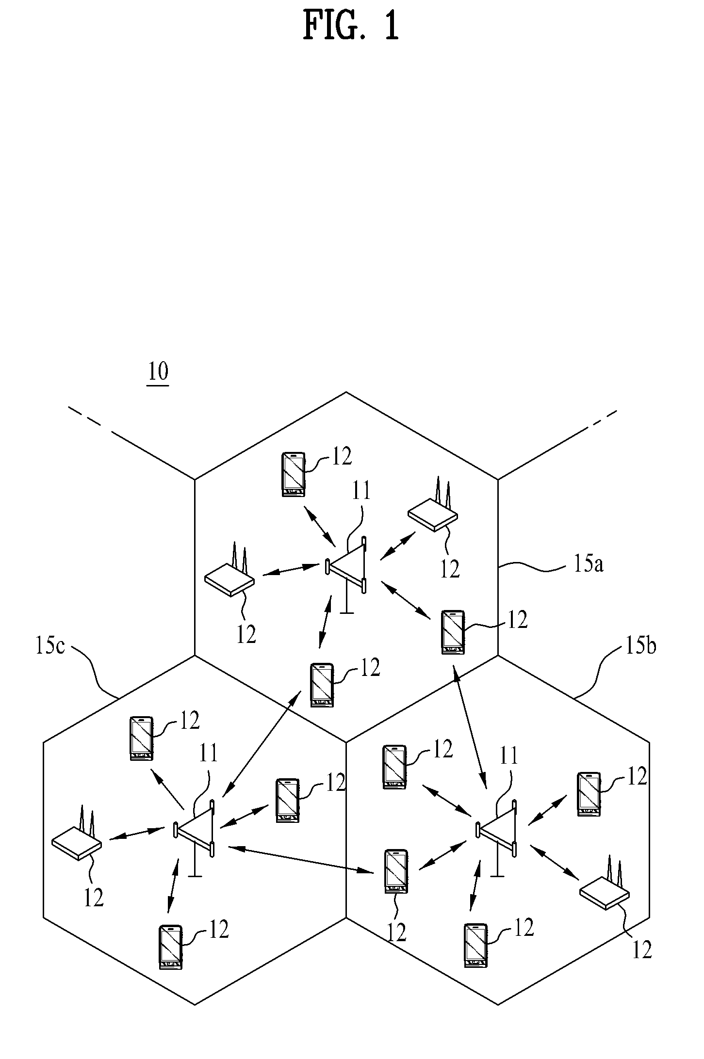
FIG. 1 is a block diagram of a wireless communication system.

Referring to FIG. 1, a wireless communication system 10 includes at least one Base Station (BS) 11. Each BS 11 provides communication service to User Equipments (UEs) 12 within a specific geographical area (generally called a cell) 15a, 15b or 15c covered by the BS 11. The cell may be further divided into a plurality of areas called sectors. The UEs 12 may be mobile or fixed devices that transmit and receive user data and / or control information to and from the BS 11. The term “UE” is interchangeable with the terms “Mobile Station (MS)”, “Mobile Terminal (MT)”, “User Terminal (UT)”, “Subscriber Station (SS)”, “wireless device”, “Personal Digital Assistant (PDA)”, “wireless modem”, “handheld device”, etc. The BS 11 is usually a fixed station that communicates with the UEs ...


PUM


Abstract

A method and apparatus for controlling uplink power in a wireless communication system are disclosed. The uplink power controlling method includes receiving target Signal-to-Interference plus Noise Ratio (SINR) parameters and an uplink noise and interference level from a base station, determining an uplink power based on a target SINR and an estimated average power level of noise and interference of a user equipment, the target SINR being determined using the target SINR parameters and the estimated average power level of noise and interference of the user equipment being calculated using the uplink noise and interference level, and receiving at least one of selectively transmitted first and second offsets from the base station and adjusting the uplink power based on the received at least one of the first and second offsets.

Description

BACKGROUND OF THE INVENTION1. Field of the InventionThe present invention relates to wireless communication, and more particularly, to a method for controlling transmission power to stably transmit data or control information to a Base Station (BS).2. Background ArtFuture-generation multimedia wireless communication systems, which are a recent active research area, require processing of various types of information including video data and wireless data at high data rates, beyond the traditional voice-oriented service.Owing to its advantage of high data rate, Orthogonal Frequency Division Multiplexing (OFDM) has recently attracted much attention. OFDM is a special case of Multi-Carrier Modulation (MCM) in which a frequency band is divided into multiple orthogonal subcarriers and data is transmitted on the subcarriers. The low complexity of OFDM reduces inter-symbol interference. In OFDM, an input serial sequence of data symbols is converted to N parallel data symbols and transmitted...

Claims


Application Information

Patent Timeline
IPC IPC(8): H04W52/04
CPCH04W52/12H04W52/146H04W52/362H04W52/243H04W52/247H04W52/241
Inventor KIM, DONG CHEOLLEE, WOOK BONGCHO, HAN GYUKWAK, JIN SAMIHM, BIN CHUL
Owner LG ELECTRONICS INC
Why Eureka
Try Eureka