Capacitance Sensor

a technology of capacitive sensors and sensors, applied in the direction of acceleration measurement using interia forces, resistance/reactance/impedence, instruments, etc., can solve the problem that failure cannot be detected immediately

Active Publication Date: 2011-05-05
HITACHI ASTEMO LTD
View PDF6 Cites 40 Cited by
  • Summary
  • Abstract
  • Description
  • Claims
  • Application Information

AI Technical Summary

Benefits of technology

[0008]As described above, it is desirable that the failure can be detected immediately when a capacitance sensor represented by the acceleration sensor fails. Accordingly

Problems solved by technology

Even in the conventional acceleration sensors having the diagnosis function for diagnosing the presence/absence of the failure, for example, a technique disclosed in the above-mentioned JP-A-2007-248328 must conduct the operation of measuring the acceleration and the operation of diagnosing the failure, separat

Method used


Image

  • Capacitance Sensor
  • Capacitance Sensor
  • Capacitance Sensor

Examples


first embodiment

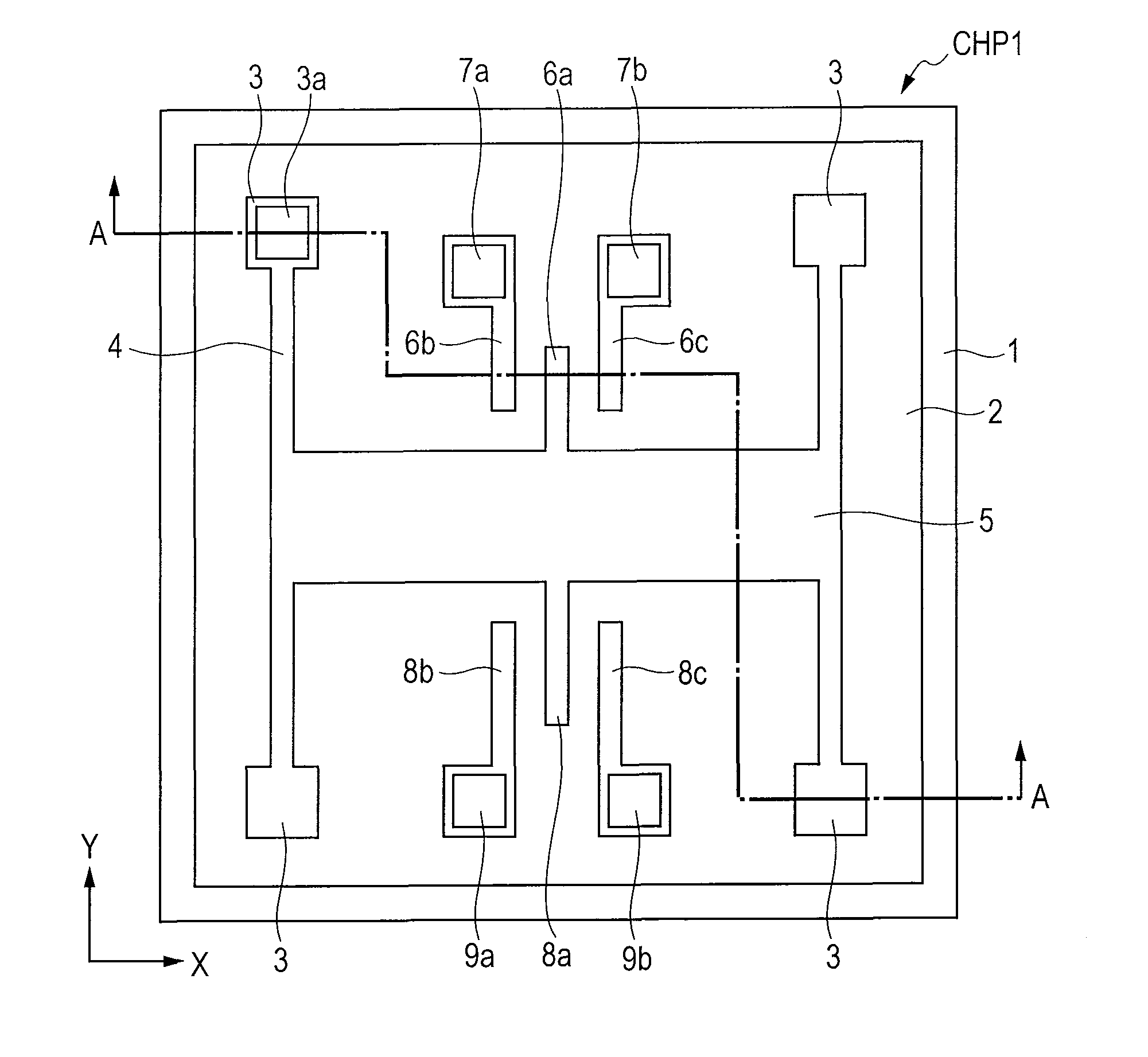
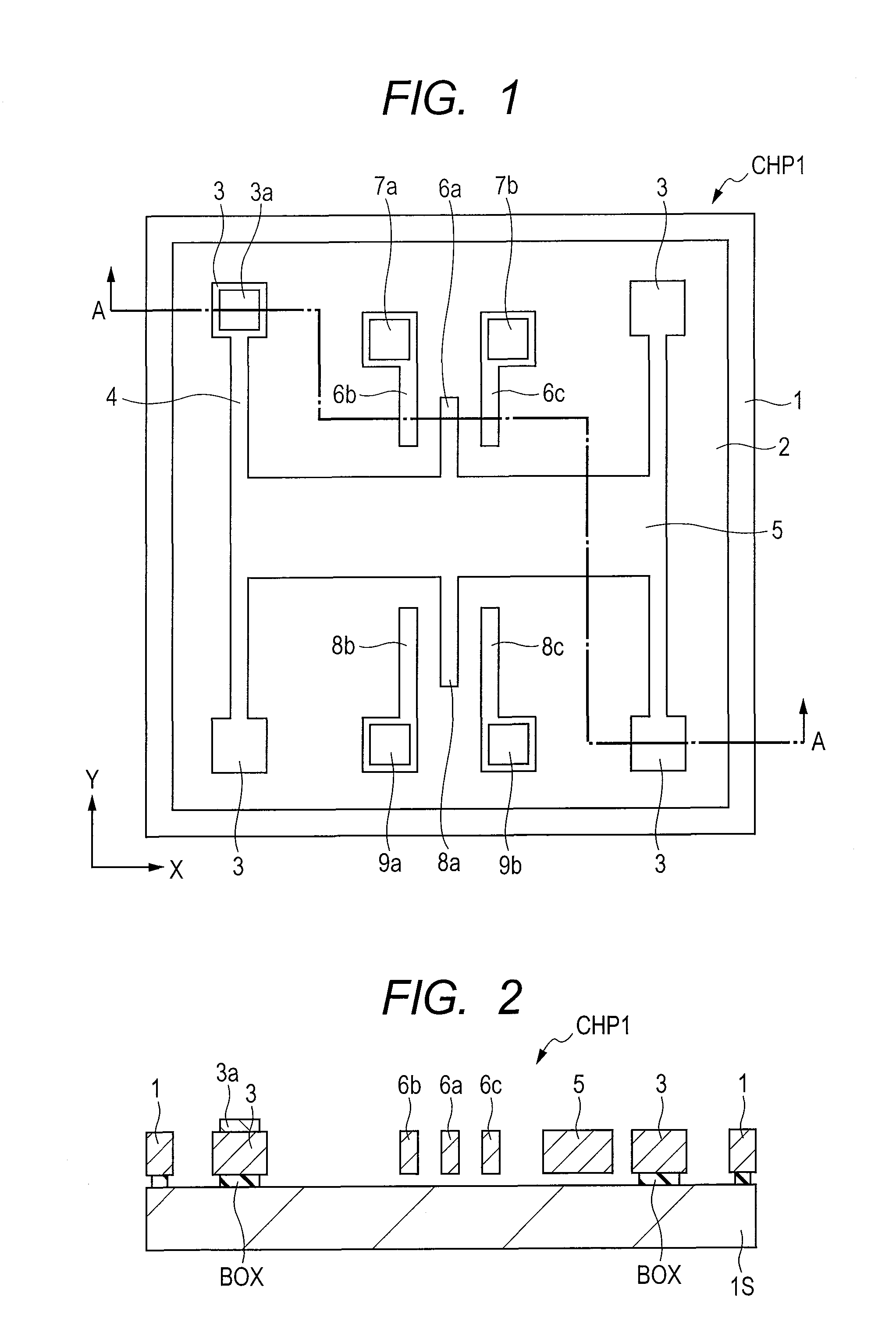
[0038]A MEMS sensor (capacitance sensor) according to a first embodiment will be described with reference to the accompanying drawings. In the first embodiment, an acceleration sensor will be described as one example of the MEMS sensor. FIG. 1 is a plan view illustrating a structure configuring the acceleration sensor formed on a semiconductor chip CHP1. As illustrated in FIG. 1, a frame part 1 is formed in the semiconductor chip CHP1, and a cavity part 2 is formed to be surrounded by the frame part 1. Fixed parts 3 are disposed inside the cavity part 2, and beams (elastic deformation parts) 4 are connected to the corresponding fixed parts 3. The beams 4 are connected with a movable part 5 which forms a weight of the acceleration sensor. That is, the fixed parts 3 and the movable part 5 are connected by the elastically deformable beams 4, and the movable part 5 can be displaced in an X-direction of FIG. 1.

[0039]The movable part 5 is formed with a detection movable electrode 6a forme...

second embodiment

[0094]An acceleration sensor according to a second embodiment will be described with reference to the accompanying drawings. FIG. 6 is a diagram illustrating the configuration of the acceleration sensor according to the second embodiment. Hereinafter, the feature of the acceleration sensor according to the second embodiment will be described, and the repetitive description of the first embodiment will be omitted.

[0095]As illustrated in FIG. 6, the feature of the acceleration sensor according to the second embodiment resides in that a high-pass filter HPF1 is disposed before the second synchronous detection unit SDU. For example, when no high-pass filter HPF1 is provided, the signals output from the first synchronous detection unit FDU include the diagnostic signal of several hundreds Hz and the voltage signal of DC to several tens Hz. Those signals are inputted to the second synchronous detection unit SDU. In the second synchronous detection unit SDU, the diagnostic signal of severa...

third embodiment

[0098]An acceleration sensor according to a third embodiment will be described with reference to the accompanying drawings. FIG. 7 is a diagram illustrating the configuration of the acceleration sensor according to the third embodiment. Hereinafter, the feature of the acceleration sensor according to the third embodiment will be described, and the repetitive description of the first embodiment will be omitted.

[0099]As illustrated in FIG. 7, the feature of the acceleration sensor according to the third embodiment resides in that not the low-pass filter LPF2 but a high-pass filter HPF2 is disposed after the second synchronous detection unit SDU. As described above, the diagnostic signal of several hundreds Hz passes through the second synchronous detection unit SDU, and is transformed into a signal of twice (cos 2wt) the frequency of the diagnostic signal, and a DC signal (cos 0). In the first embodiment, the low-pass filter LPF2 is used to extract the D signal (cos 0) for conducting ...


PUM


Abstract

A technique in which a false detection and a wrong diagnosis can be suppressed in a capacitance sensor represented by an acceleration sensor is provided. A first capacitative element and a second capacitative element, which configure a capacitance detection unit, and a third capacitative element and a fourth capacitative element, which configure a forced oscillation generation unit, are electrically separated from each other. That is, the diagnosis movable electrode that configures the third capacitative element and the fourth capacitative element is formed integrally with the movable part. On the other hand, the diagnosis fixed electrode and the diagnosis fixed electrode are electrically separated from the detection fixed electrode and the detection fixed electrode.

Description

CLAIM OF PRIORITY[0001]The present application claims priority from Japanese patent application JP 2009-249424 filed on Oct. 29, 2009, the content of which is hereby incorporated by reference into this application.FIELD OF THE INVENTION[0002]The present invention relates to a capacitance sensor, and more particularly to a technique that is effectively applied to a capacitance sensor having a diagnosis function for determining whether a failure (abnormality) occurs, or not.BACKGROUND OF THE INVENTION[0003]An acceleration sensor which is one of MEMS (micro electro mechanical systems) sensors is made up of a weight (movable part) and a support beam (elastic deformation part), and converts acceleration exerted on the weight into an electric signal. The MEMS sensors of this type include a capacitance sensor that detects the acceleration as a capacitance change between electrodes configuring a capacitor. The capacitance sensor captures the acceleration exerted on the weight as a change in...

Claims


Application Information

Patent Timeline
IPC IPC(8): G01P15/125G01P15/08G01P21/00
CPCG01C19/5719G01P2015/0814G01P21/00G01P15/125
Inventor JEONG, HEEWONYAMANAKA, KIYOKOGOTO, YASUSHINAKAMURA, TOSHIAKIHAYASHI, MASAHIDE
Owner HITACHI ASTEMO LTD
Why Eureka
Try Eureka