Sealed container

Inactive Publication Date: 2011-05-05
THREADLESS CLOSURES
View PDF2 Cites 15 Cited by
  • Summary
  • Abstract
  • Description
  • Claims
  • Application Information

AI Technical Summary

Benefits of technology

References to foil herein include impervious laminates comprising one or more layers which give the foil strength and one or more layers for attaching the upper and/or lower surface of the foil to another article. Such foils are widely used in other fields. Where the foil is to be secured by induction heating, an electrically conductive layer is required. This is usually a metallic layer and most commonly a layer of aluminium. The electrically conductive layer is typically provided with one or more plastic coatings, e.g. of polyethylene, which melt when the electrically conductive layer is heated to bond the foil to an article held in contact therewith. Such foils can be bonded to both glass and plastic articles. Preferably, the foil is constructed so that it can be pre-shaped to facilitate easy assembly of the closure means and bonding to the container body.
The foil is preferably secured to the container in a manner capable of withstanding elevated internal pressures. Laminated foils comprising two or more layer

Problems solved by technology

Despite the tremendous advantages that such a beverage container would provide for drinks suppliers, container manufacturers and consumers alike, no successful beverage container that fulfils these aims has yet been produced.
This is because there are significant technical problems associated with wide-mouth containers to overcome, and no practical solution to th

Method used


Image

  • Sealed container
  • Sealed container
  • Sealed container

Examples


Example

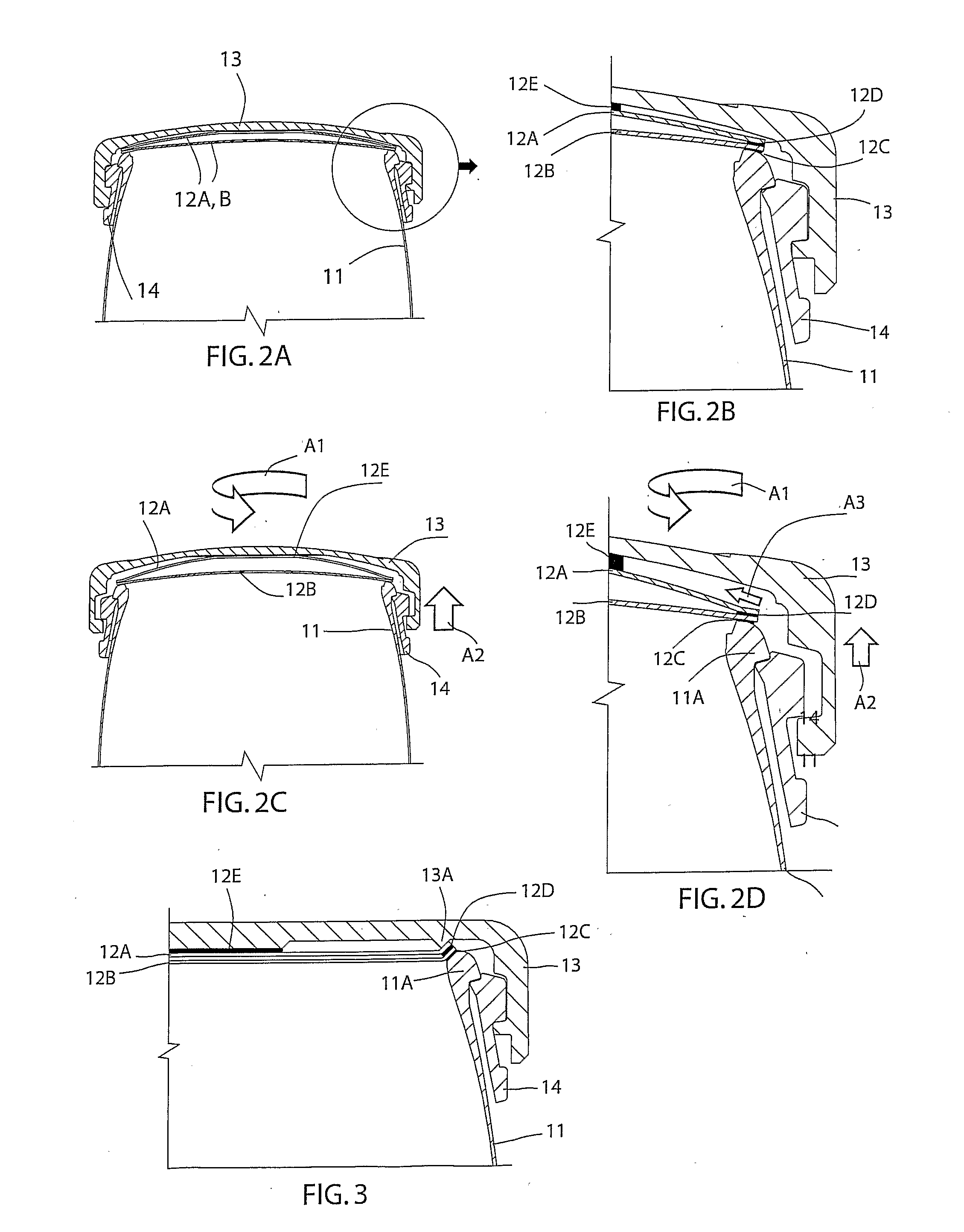
FIG. 2 illustrates a second embodiment having a container body 11, a double layer foil 12 instead of a folded back foil, a cap 13 and collar 14.

The foil 12 comprises an upper foil 12A and a lower foil 12B. The lower foil 12A is welded to the top of the lip 11A of the container body along weld line 12C. The upper foil 12A has its lower surface welded to the upper surface of the lower foil 12B around the perimeter thereof along weld line 12D (see FIG. 2B) and has its upper surface welded to the interior of the cap 13 at a weld area 12E radially inward of the weld lines 12C and 12D.

The upper and lower foil 12A, 12B are thus bonded to each other only around their perimeter and so form an empty pillow, e.g. in the form of an empty, circular tea-bag. To prevent the internal surfaces of the upper and lower foils 12A, 12B bonding to each other these are preferably formed by aluminium layers (except in the area of weld line 12D).

When the cap 12 is rotated in the loosening direction (indicate...

Example

FIGS. 8A-8F illustrate a sixth embodiment which is a further development of that shown in FIG. 3 above.

In this embodiment, a pre-formed foil 52 is mechanically secured to the underside of a cap 53 by engaging apertures 52A in the foil over projections 53A on the underside of the cap 53 and then pressing a securing plate 55 onto the projections 53A so a central portion of the foil is clamped to the underside of the cap 53. Other forms of mechanical connection may be used. The projections 53A may, for example, be hot-studded once the foil 52 is in place so as to enlarge their heads so the foil cannot be removed therefrom. An adhesive connection or welded bond may also be used (as in the embodiments described above).

An annular projection 53B is also provided on the underside of the cap 53 to form a bore seal which fits against the interior of a container body (as described further below).

The foil 52 is preferably, pre-formed so that an outer portion thereof fits around the bore seal 53...


PUM


Abstract

A container (1) for the storage of a carbonated drink, comprising a container body with an opening that defines an axis and a removable closure (3) for closing the opening, the closure including a foil (2) for bonding to the container to close the opening in a gas-tight manner, the foil also being connected to, or interacting with, the closure, such that initial rotation of the closure in a loosening direction relative to the container body distorts or deforms the foil in a manner such that further rotation of the. closure results in a peel force being applied to the bond between the foil and the container.

Description

TECHNICAL FIELDThe present invention relates to containers, and particularly relates to containers for supplying beverages to consumers. The invention has particular utility for the storage and supply of carbonated and other sparkling drinks, but may also be used with other types of drinks or other contents.BACKGROUND ARTFor many years there has been a desire among drinks suppliers and container manufacturers to provide practical wide-mouth beverage supply containers which consumers may drink from comfortably in the same manner as from a drinks glass or other drinking vessel, particularly in relation to carbonated drinks such as beers, etc. Despite the tremendous advantages that such a beverage container would provide for drinks suppliers, container manufacturers and consumers alike, no successful beverage container that fulfils these aims has yet been produced. Consequently, bottles and ring-pull cans currently remain the main practical beverage supply containers for consumers. Thi...

Claims


Application Information

Patent Timeline
IPC IPC(8): B65D51/18B65D41/00
CPCB65D51/228B65D41/08B65D2251/0093B65D2251/0018
Inventor FRASER, ANTHONY HENRY JOSEPHHEIN, JOHN
Owner THREADLESS CLOSURES
Why Eureka
Try Eureka