Aircraft starter generator
Active Publication Date: 2011-05-05
KAWASAKI HEAVY IND LTD
10 Cites 48 Cited by
AI-Extracted Technical Summary
Problems solved by technology
View moreMethod used
View moreBenefits of technology
View moreAbstract
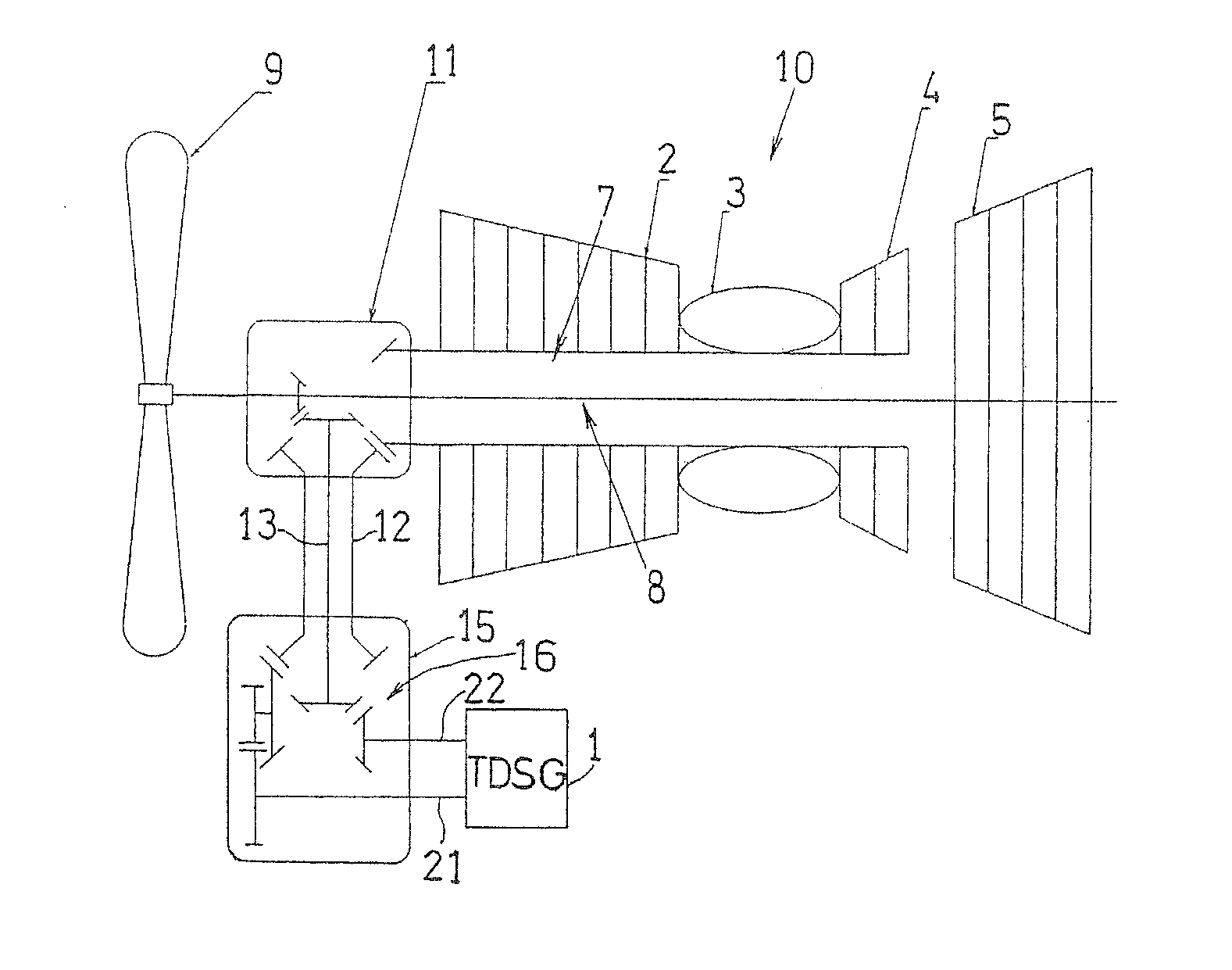
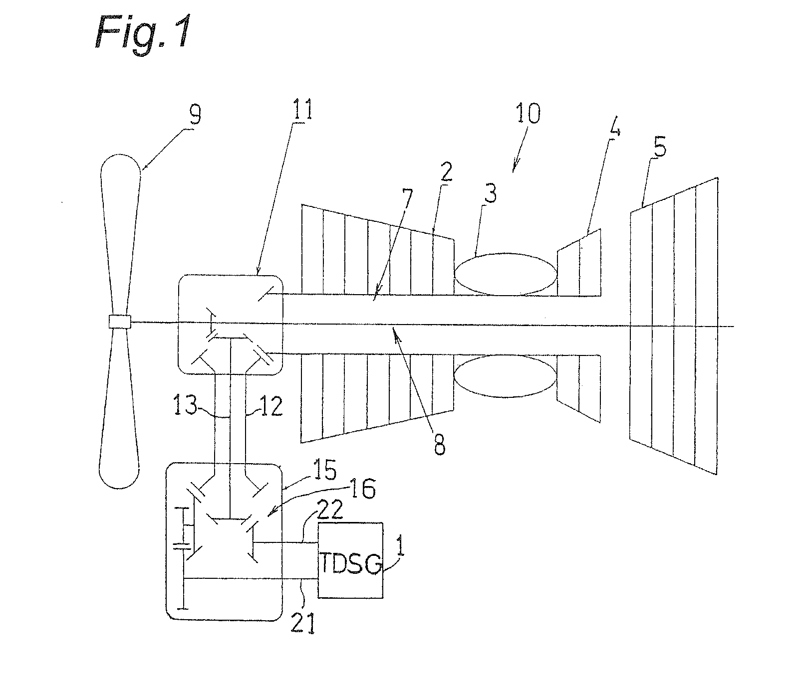
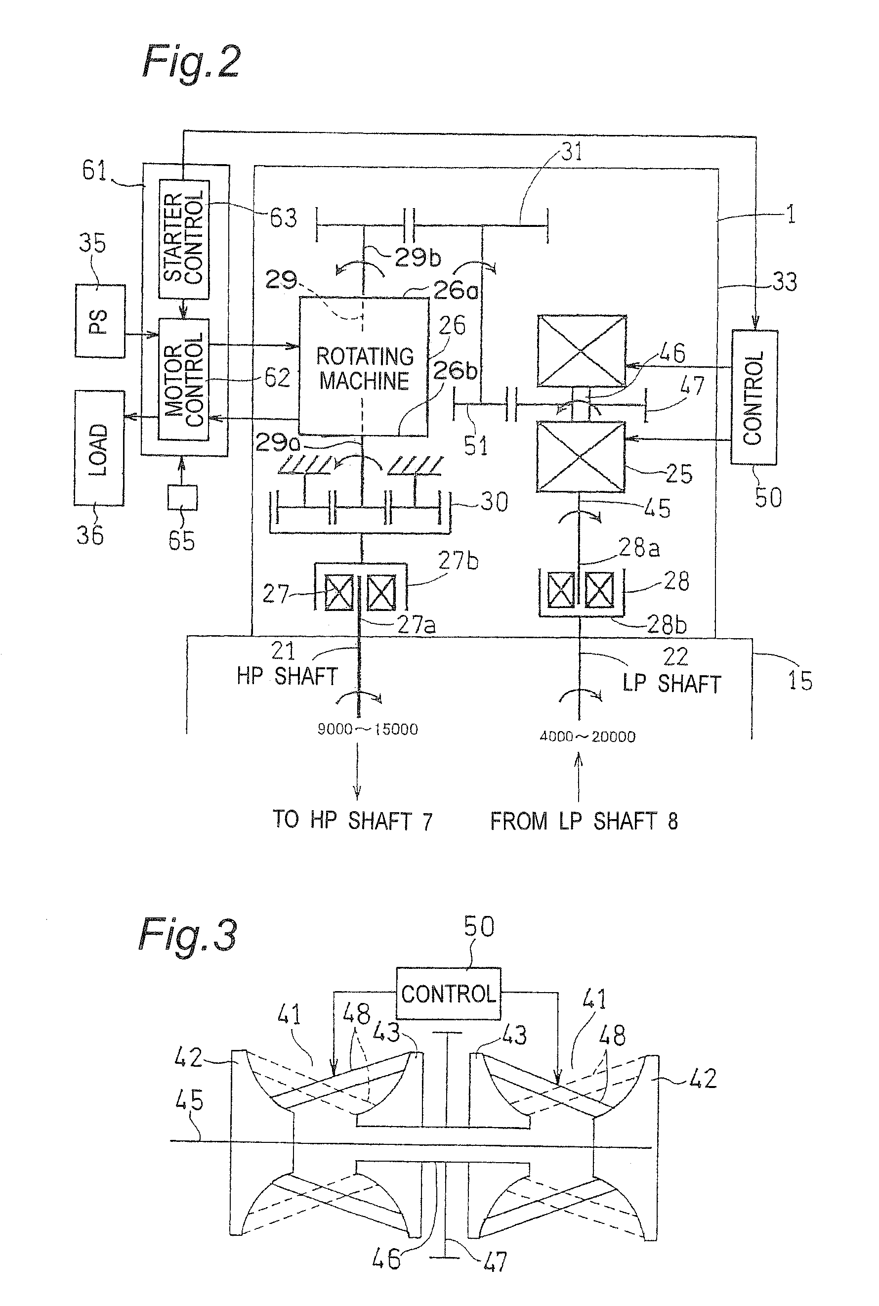
A starter generator has an electric rotating machine having a rotating shaft and designed to carry two reverse operations—motor and generator. A first clutch is connected between the rotating machine and the first rotating shaft for transmitting rotations of the rotating machine to the first rotating shaft. A second clutch is connected between the rotating machine and the second rotating shaft for transmitting rotations of the second rotating shaft to the rotating machine. A continuously variable transmission is provided for changing the number of rotations transmitted from the second rotating shaft to the rotating machine. The rotating machine is supplied with electric power to rotate the rotating shaft, or the number of rotations of the rotating shaft is kept constant by controlling a transmission ratio of the continuously variable transmission.
Application Domain
Technology Topic
Image
Examples
- Experimental program(2)
Example
Example
Login to view more PUM


Description & Claims & Application Information
We can also present the details of the Description, Claims and Application information to help users get a comprehensive understanding of the technical details of the patent, such as background art, summary of invention, brief description of drawings, description of embodiments, and other original content. On the other hand, users can also determine the specific scope of protection of the technology through the list of claims; as well as understand the changes in the life cycle of the technology with the presentation of the patent timeline. Login to view more.
Login to view more Similar technology patents
Curtain airbag arrangement structure
InactiveUS20060082108A1Enhance assemble workability and productivitySimplify structurePedestrian/occupant safety arrangementInterior spaceSide impact
Owner:MAZDA MOTOR
Rack assist type electric power steering system
InactiveUS20100319471A1Simplify structureReduction in partGear vibration/noise dampingBall bearingsElectrical and Electronics engineeringElectric power steering
Owner:HL MANDO CORP
Belt conveyor unit and image forming apparatus
ActiveUS20140339056A1Prevent decrease in durabilitySimplify structureConveyorsElectrographic process apparatusEngineeringFlange
Owner:CANON KK
Solar module window shade apparatus and method
InactiveUS20110186104A1Simplify structureLower costPV power plantsPhotovoltaic energy generationEngineeringSolar module
Owner:SOLARIA CORP
Cell culture device having culture medium replacement function
ActiveUS20150010996A1Downsize apparatusSimplify structureBioreactor/fermenter combinationsBiological substance pretreatmentsBiologyCulture cell
Owner:JTEC
Classification and recommendation of technical efficacy words
- Production cost be reduce
- Simplify structure
Low thermal resistance LED package
ActiveUS20060091410A1Reduce thermal resistanceProduction cost be reduceSolid-state devicesSemiconductor devicesEngineeringThin metal
Owner:PROLIGHT OPTO TECH +1
Process for the preparation of cyclic esters and method for purification of the same
Owner:KUREHA KAGAKU KOGYO KK
Electrical connector
InactiveUS7850473B1Production cost be reduceEffectively adjustEngagement/disengagement of coupling partsCoupling contact membersElectrical and Electronics engineeringElectrical connector
Owner:DAIICHI SEIKO CO LTD
Toner cartridge
ActiveUS20060171744A1Reduce number of componentProduction cost be reduceElectrographic process apparatusPhysicsWindow shutter
Owner:KYOCERA DOCUMENT SOLUTIONS INC