Reconfigurable Inductive to Synchronous Motor

Active Publication Date: 2011-05-05
MOTOR GENERATOR TECH INC
View PDF12 Cites 12 Cited by
  • Summary
  • Abstract
  • Description
  • Claims
  • Application Information

AI Technical Summary

Benefits of technology

[0007]The present invention addresses the above and other needs by providing a reconfigurable electric motor which includes a rotor containing rotatable permanent magnets or non-magnetically conducting shunting pieces. The magnets and/or shunting pieces have a first position producing a weak magnetic field for asynchronous induction motor operation at startup and a second position producing a strong magnetic field for efficient synchronous operation. The motor includes a squirrel cage for induction motor operation at startup with the permanent magnets

Problems solved by technology

Unfortunately, low power induction motors are not highly efficient, and lose efficiency under reduced loads because the amount of power consumed by the stator remains constant at low loads.
Unfortunately, the per

Method used


Image

  • Reconfigurable Inductive to Synchronous Motor
  • Reconfigurable Inductive to Synchronous Motor
  • Reconfigurable Inductive to Synchronous Motor

Examples


first embodiment

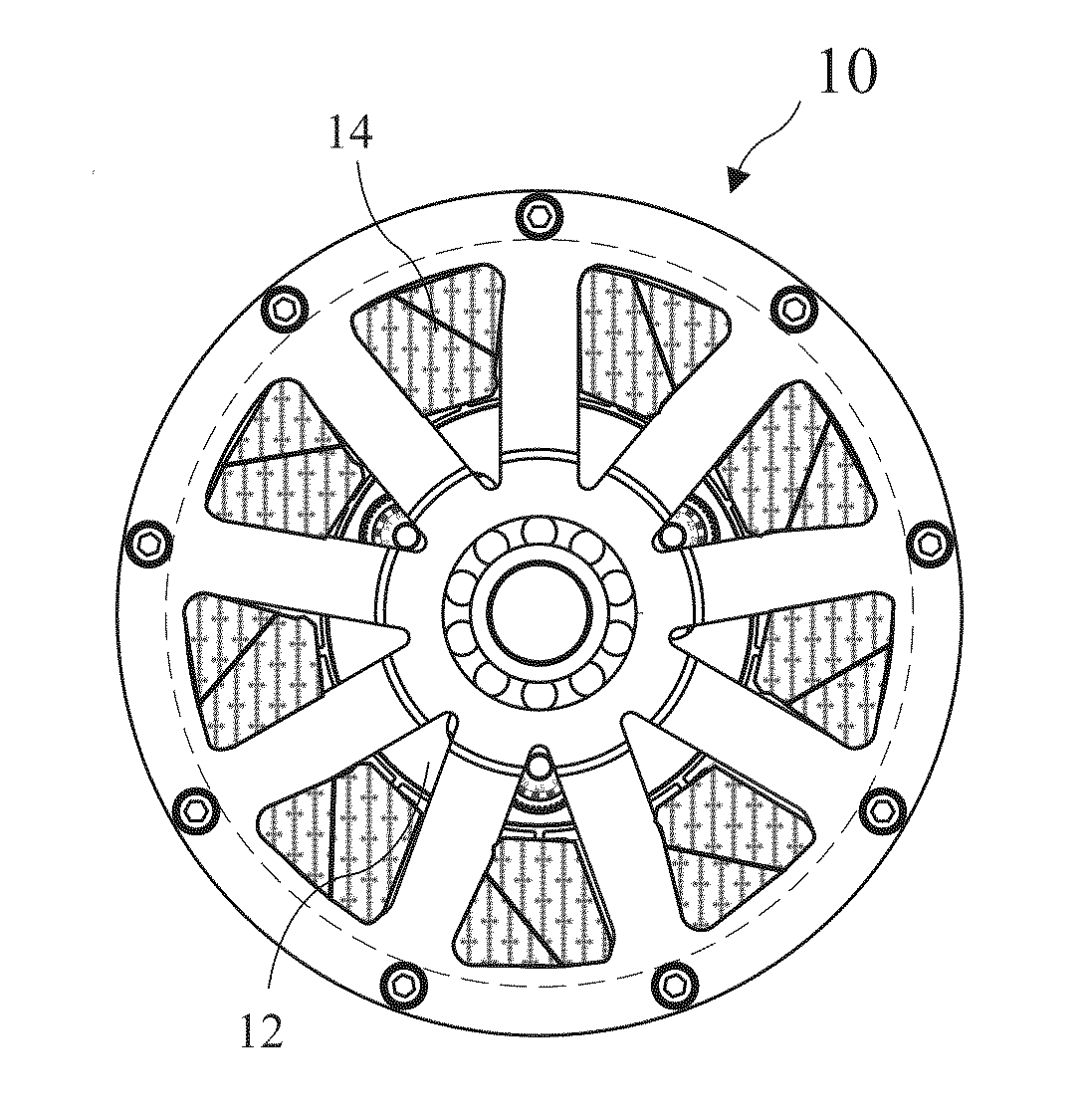
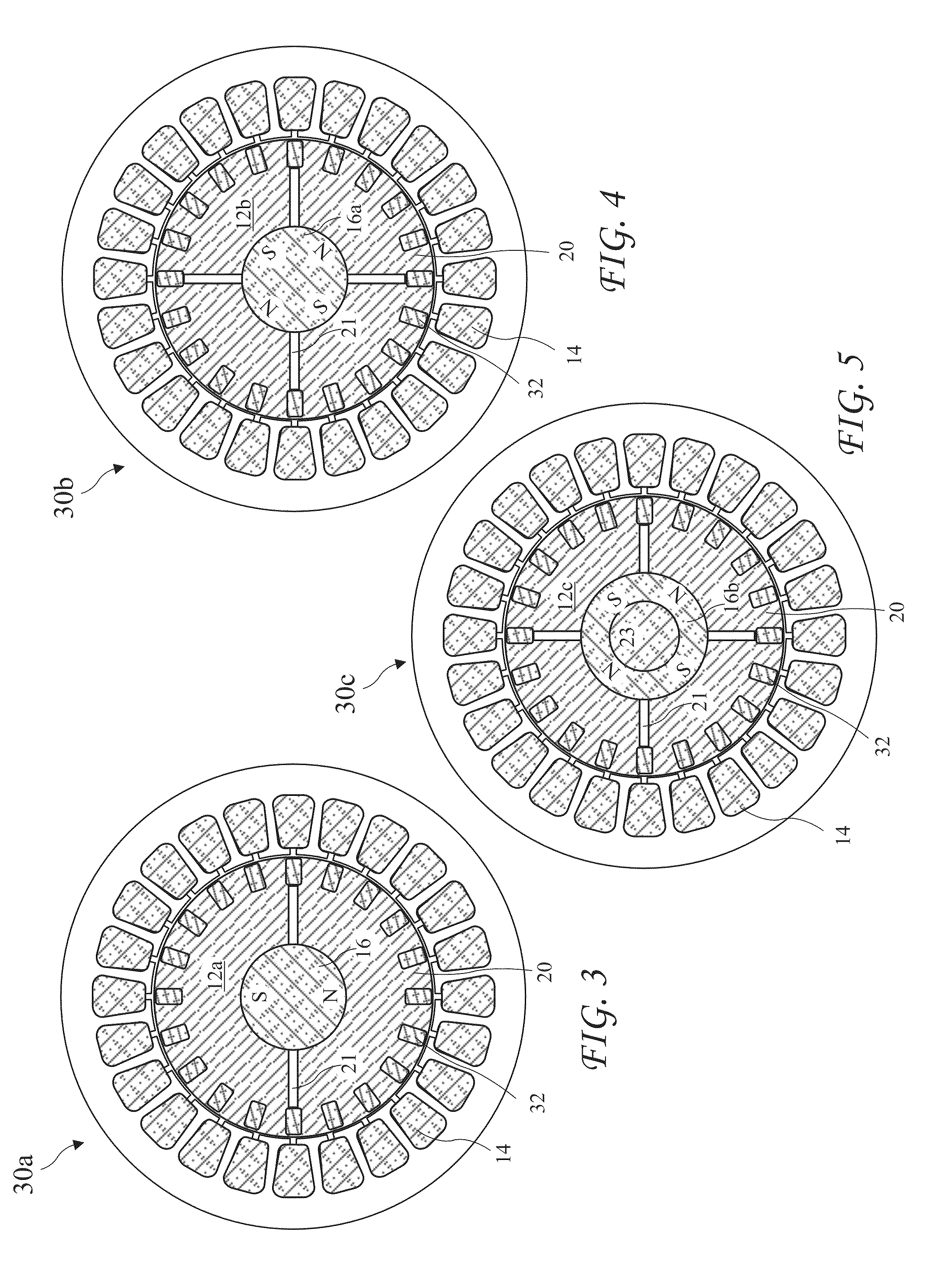
[0071]A cross-sectional view of the reconfigurable electric motor 10 taken along line 3-3 of FIG. 2 showing the motor 10 comprising a two pole motor 30a with a single two pole rotatable Interior Permanent Magnet (IPM) 16 in the rotor 12a is shown residing coaxial with the motor shaft 11 in FIG. 3. The magnet 16 is shown with air gaps 21 on each side of the magnet 16 splitting the North (N) and South (S) poles of the magnet 16 in a radially aligned configuration. Bars 32 of a squirrel cage element for inductive operation are angularly spaced apart around the outer radius of the rotor 12 reaching the length of the rotor 12. The bar may be straight or may be twisted to reduce noise among other benefits. The magnet 16 and rods 32 are carried by rotor pole pieces 20 separated by the air gaps 21. The pole pieces 20 are preferably constructed from laminated layers of individually insulated magnetically conducting material, for example, iron or steel.

second embodiment

[0072]A cross-sectional view of the reconfigurable electric motor 10 according to the present invention taken along line 3-3 of FIG. 2 showing the motor 10 comprising a four pole motor 30b with a single four pole rotatable permanent magnet 16a residing coaxial with the motor shaft 11 in a radially aligned rotor 12b configuration is shown in FIG. 4. The pole piece 20 is divided into four quarter sections with air gaps 21 between adjacent sections. The motor 30b is otherwise like the motor 30a.

third embodiment

[0073]A cross-sectional view of the reconfigurable electric motor 10 according to the present invention taken along line 3-3 of FIG. 2 showing the motor 10 comprising a four pole motor 30c with a rotor 12c having a single hollow four pole rotatable permanent magnet 16b residing coaxial with the motor shaft 11 in a radially aligned rotor configuration is shown in FIG. 5. A steel shaft 23 runs through the center of the hollow magnet 16b. The motor 30c is otherwise like the motor 30b.

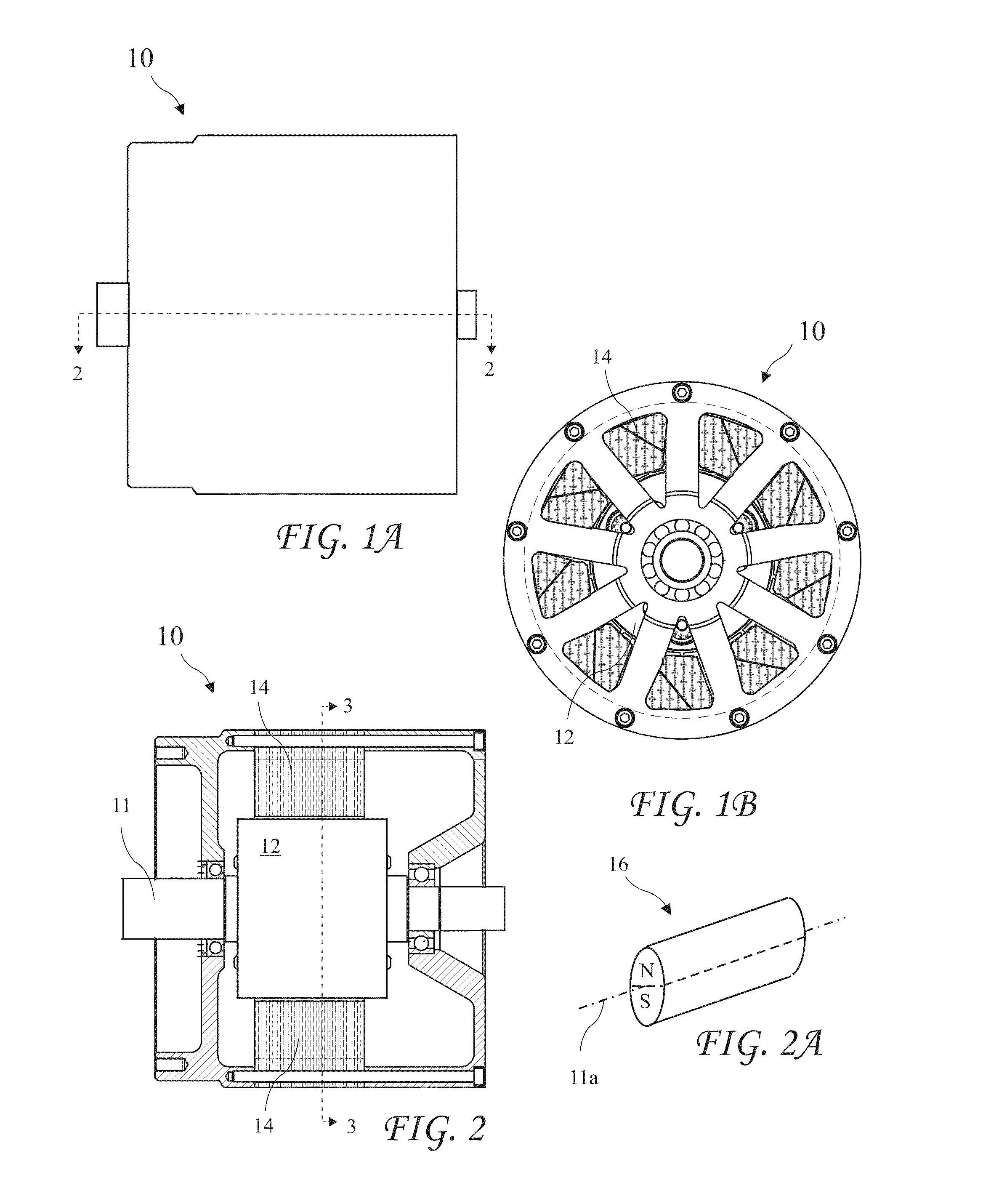
[0074]A perspective view of a cylindrical two pole permanent magnet 16 suitable for use with the present invention is shown in FIG. 2A. The magnet 16 has a magnet axis 11a. While a cylindrical magnet is a preferred shape for a rotating magnet according to the present invention, other shapes may be adapted to be moveable to obtain the benefit of the present invention and an electric motor having moveable magnets of any shape configured to adjust a rotor magnetic field to a weak magnetic field for asynchron...


PUM


Abstract

A reconfigurable electric motor includes a rotor containing rotatable permanent magnets or non-magnetically conducting shunting pieces. The magnets and/or shunting pieces have a first position producing a weak magnetic field for asynchronous induction motor operation at startup and a second position producing a strong magnetic field for efficient synchronous operation. The motor includes a squirrel cage for induction motor operation at startup with the permanent magnets and/or shunting pieces positioned to product the weak magnetic field to not interfere with the startup. When the motor approaches or reaches synchronous RPM, the permanent magnets and/or shunting pieces rotate to produce a strong magnetic field for high efficiency synchronous operation. The position of the magnets and/or shunting pieces may be controlled by a centrifugal mechanism, or viscous damping may delay rotation of the magnets and/or shunting pieces, or electrically controlled apparatus may control positions of the magnets and/or shunting piece.

Description

[0001]The present application is a Continuation In Part of U.S. patent application Ser. No. 12 / 610,184 filed Oct. 30, 2009, and of U.S. patent application Ser. No. 12 / 610,271 filed Oct. 30, 2009, which applications are incorporated in their entirety herein by reference.BACKGROUND OF THE INVENTION[0002]The present invention relates to electric motors and in particular to moveable permanent magnets, and / or non-magnetically conducting shunting pieces, in a rotor to reconfigure the motor from an asynchronous induction motor at startup into a synchronous motor for efficient operation.[0003]A preferred form of electric motors are brushless AC induction motors. The rotors of induction motors include a cage (or squirrel cage resembling a “hamster wheel”) rotating inside the stator. The cage comprises axially running bars angularly spaced apart on the outer perimeter of the rotor. An AC current provided to the stator introduces a rotating stator magnetic field in the stator, and the rotating...

Claims


Application Information

Patent Timeline
IPC IPC(8): H02K21/46
CPCH02K7/116H02K21/46H02K21/028
Inventor FINKLE, LOUIS J.FURIA, ANDREA
Owner MOTOR GENERATOR TECH INC
Why Eureka
Try Eureka