Hardware synchronization method of cascading instrument

An inter-instrument and instrument technology, applied in the field of control and testing, can solve the problems of frequent time synchronization, low synchronization operation accuracy, and large difference influence, and achieve the effect of small transmission delay, simplified control process and structure, and fast triggering.

Active Publication Date: 2013-04-24
杭州亿恒科技有限公司
View PDF5 Cites 8 Cited by
  • Summary
  • Abstract
  • Description
  • Claims
  • Application Information

AI Technical Summary

Problems solved by technology

This method is mainly to solve the problem that the synchronous operation accuracy of each instrument in the system in the prior art is not high, and is greatly affected by the individual differences of the crystal oscillators of each instrument.
Secondly, it can also solve the problem of frequent time synchronization in the prior art in order to eliminate the cumulative error caused by the difference in crystal oscillators after the system is synchronized, so that only one synchronization operation is required to achieve a long-term stable synchronization state

Method used


Image

  • Hardware synchronization method of cascading instrument
  • Hardware synchronization method of cascading instrument
  • Hardware synchronization method of cascading instrument

Examples


Embodiment Construction

[0029] In order to make the technical means, creative features, goals and effects achieved by the present invention easy to understand, the present invention will be further described below in conjunction with specific illustrations.

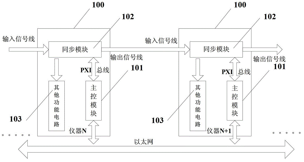
[0030] Such as figure 1 As shown, this figure is the composition of the hardware system structure during the specific implementation of the method of the present invention. It includes a plurality of instruments 100 with a main control module 101 and a synchronization module 102, and an input signal line and an output signal line for connecting the synchronization module 102 in the instrument 100; the main control module 101 and the synchronization module 102 of the instrument 100 pass through the instrument The main control module 101 of the instrument 100 realizes the distributed connection communication between the instruments through Ethernet; the synchronization module 102 in the instrument 100 is also connected to other functional circuits...


PUM


Abstract

The invention discloses a hardware synchronization method of a cascading instrument. The hardware synchronization method of the cascading instrument includes that main control modules of a plurality of instruments conduct information interaction through Ethernet, distribute addresses according to position order of a series link which is formed by connecting synchronous modules, and confirm an instrument which is located in a first position in the link. When synchronization needs to be conducted, the main control module of the first position instrument sends synchronous configuration requirements to the main control modules of other position instruments through the Ethernet and sends synchronous instructions to the synchronous modules of the instrument. The other instrument main control modules receive the synchronous configuration requirements through the Ethernet, finish synchronous configuration of the instrument, and meanwhile the synchronous modules of the instrument receive synchronous input signals and clock input signals through an input signal wire. After the synchronous input signals and the clock input signals are processed by the synchronous modules in the instrument, one path sends out the synchronous input signals and the clock input signals through the output signal wire and the other path is led to other function circuits of the instrument to conduct synchronization operation, so synchronization of all instruments in a system can be finally achieved.

Description

Technical field: [0001] The invention relates to the technical fields of control and testing, in particular to a synchronization method between control and testing instruments which can be cascaded in large-scale control and testing systems. Background technique: [0002] In the field of control and testing technology, especially the extraction of complex state information and analog calculation, it not only requires a huge number of signal acquisition links, but also requires strict synchronization of multiple signal acquisition links. It is obviously impossible for a traditional single instrument to fully meet its increasing application requirements. For this reason, it has become an inevitable trend to adopt cascading or distributed connections of multiple instruments, and the synchronous processing of signal acquisition links between multiple instruments has also become unavoidable factor. [0003] At present, whether it is cascaded or distributed, there are two main te...

Claims


Application Information

Patent Timeline
Patent Type & Authority Applications(China)
IPC IPC(8): H04L7/00
Inventor 贺惠农秦巍黄连生
Owner 杭州亿恒科技有限公司
Why Eureka
Try Eureka