
Hybrid Electric Motor with Self Aligning Permanent Magnet and Squirrel Cage Rotors

a permanent magnet, hybrid technology, applied in the direction of dynamo-electric machines, magnetic circuit rotating parts, magnetic circuit shapes/forms/construction, etc., can solve the problems of low power induction motors that are not highly efficient at designed operating speed, less efficient under reduced loads, and limited size of permanent magnets, so as to improve the sequence of inductive startup and efficient synchronous operation

Active Publication Date: 2015-07-09
MOTOR GENERATOR TECH INC
View PDF16 Cites 7 Cited by
  • Summary
  • Abstract
  • Description
  • Claims
  • Application Information

AI Technical Summary

Benefits of technology

The invention provides an improved design for a motor that includes a rotor with slots and permanent magnets. The slots match the spacing of the magnets in an outer rotor, allowing the magnets to create poles that connect to the inner rotor without needing a mechanical coupling. The design also includes first and second bars that work together to quickly reach synchronous RPM and increase the torque output of the motor. The technical effects include improved performance and efficiency of the motor.

Problems solved by technology

Unfortunately, low power induction motors are not highly efficient at designed operating speed, and are even less efficient under reduced loads because the amount of power consumed by the stator remains constant at such reduced loads.
Unfortunately, the permanent magnets are limited in size because if the permanent magnets are too large, they prevent the motor from starting.
Such size limitation limits the benefit obtained from the addition of the permanent magnets.

Method used


Image

  • Hybrid Electric Motor with Self Aligning Permanent Magnet and Squirrel Cage Rotors
  • Hybrid Electric Motor with Self Aligning Permanent Magnet and Squirrel Cage Rotors
  • Hybrid Electric Motor with Self Aligning Permanent Magnet and Squirrel Cage Rotors

Examples


Embodiment Construction

[0024]The following description is of the best mode presently contemplated for carrying out the invention. This description is not to be taken in a limiting sense, but is made merely for the purpose of describing one or more preferred embodiments of the invention. The scope of the invention should be determined with reference to the claims.

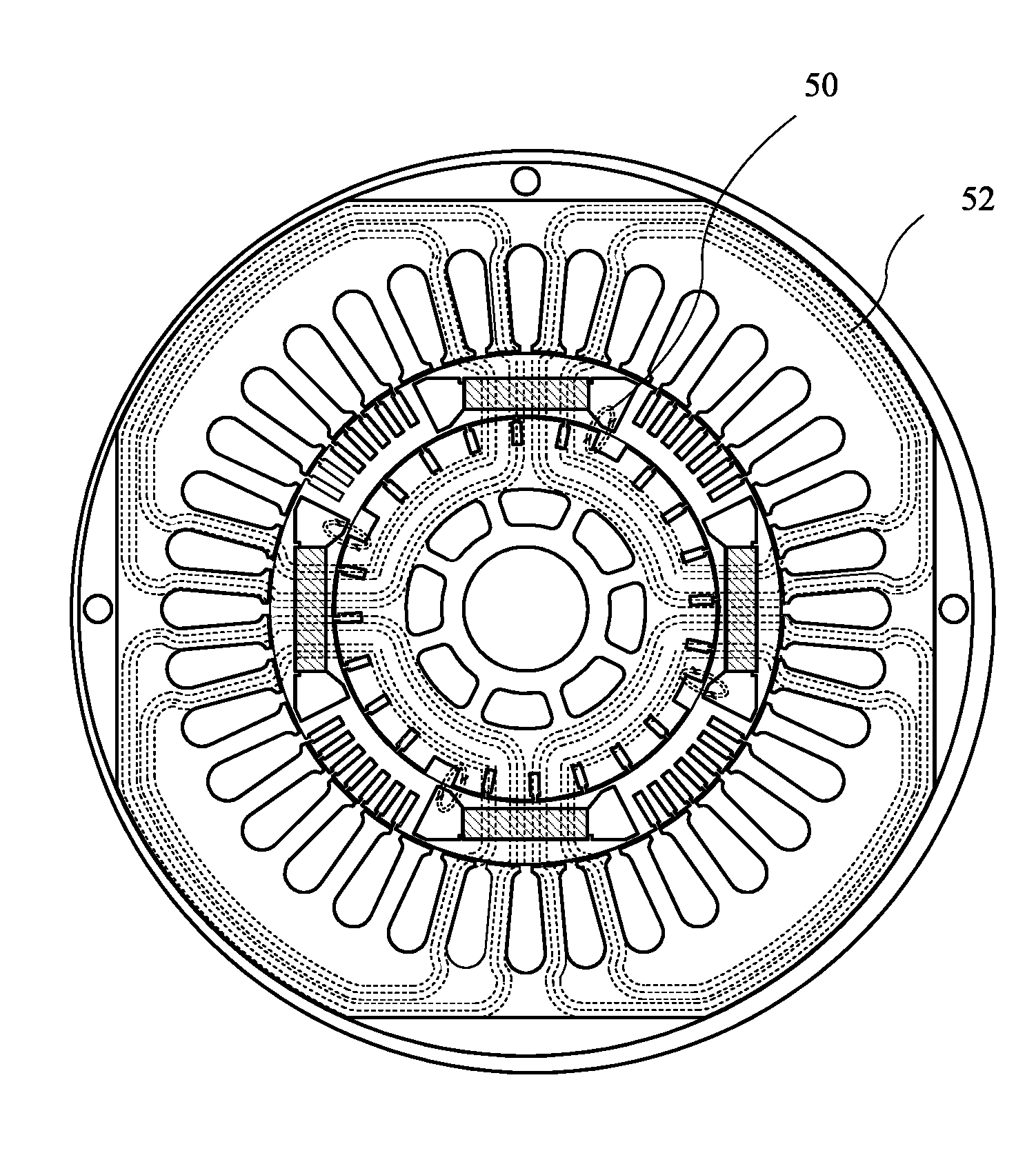
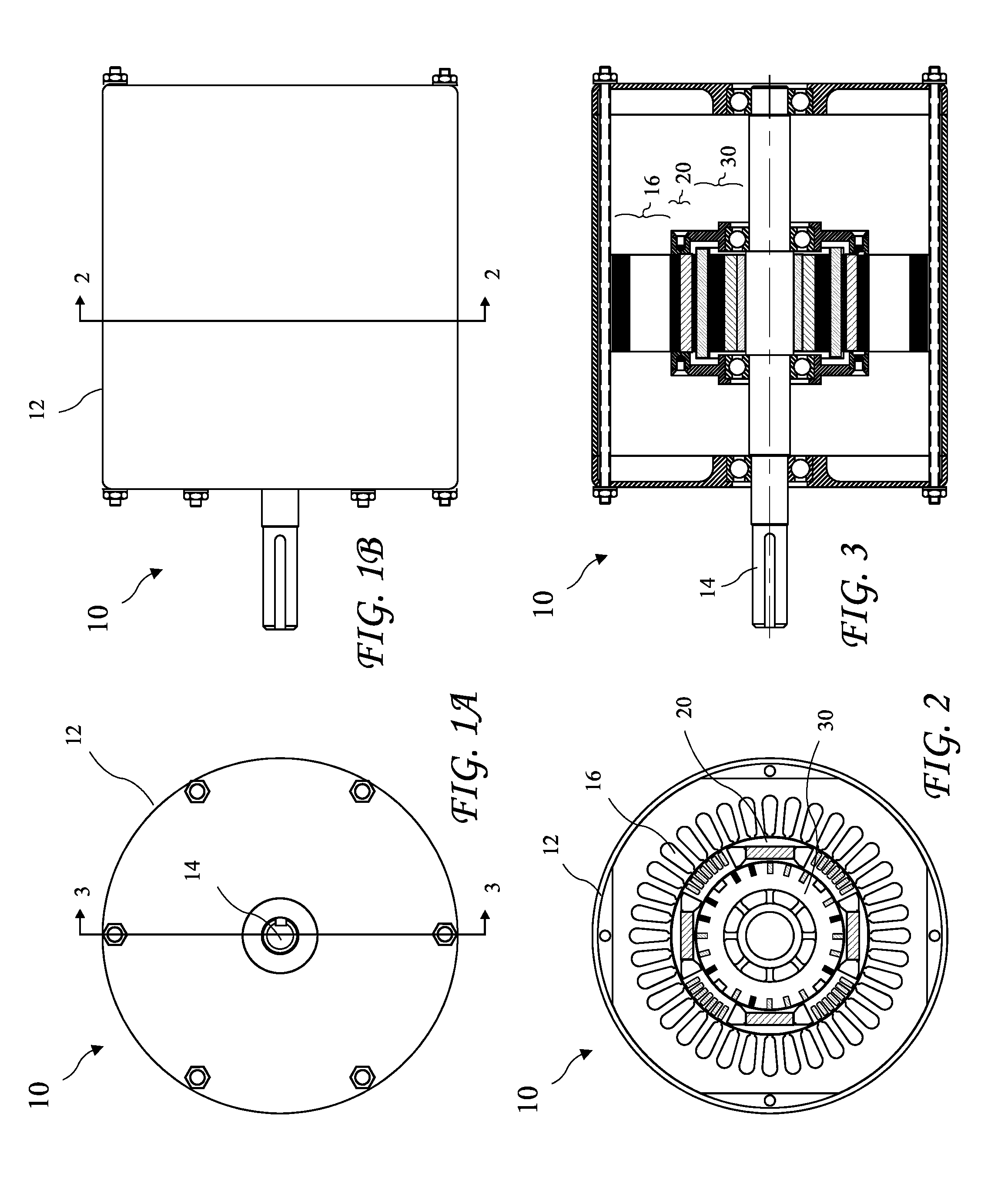
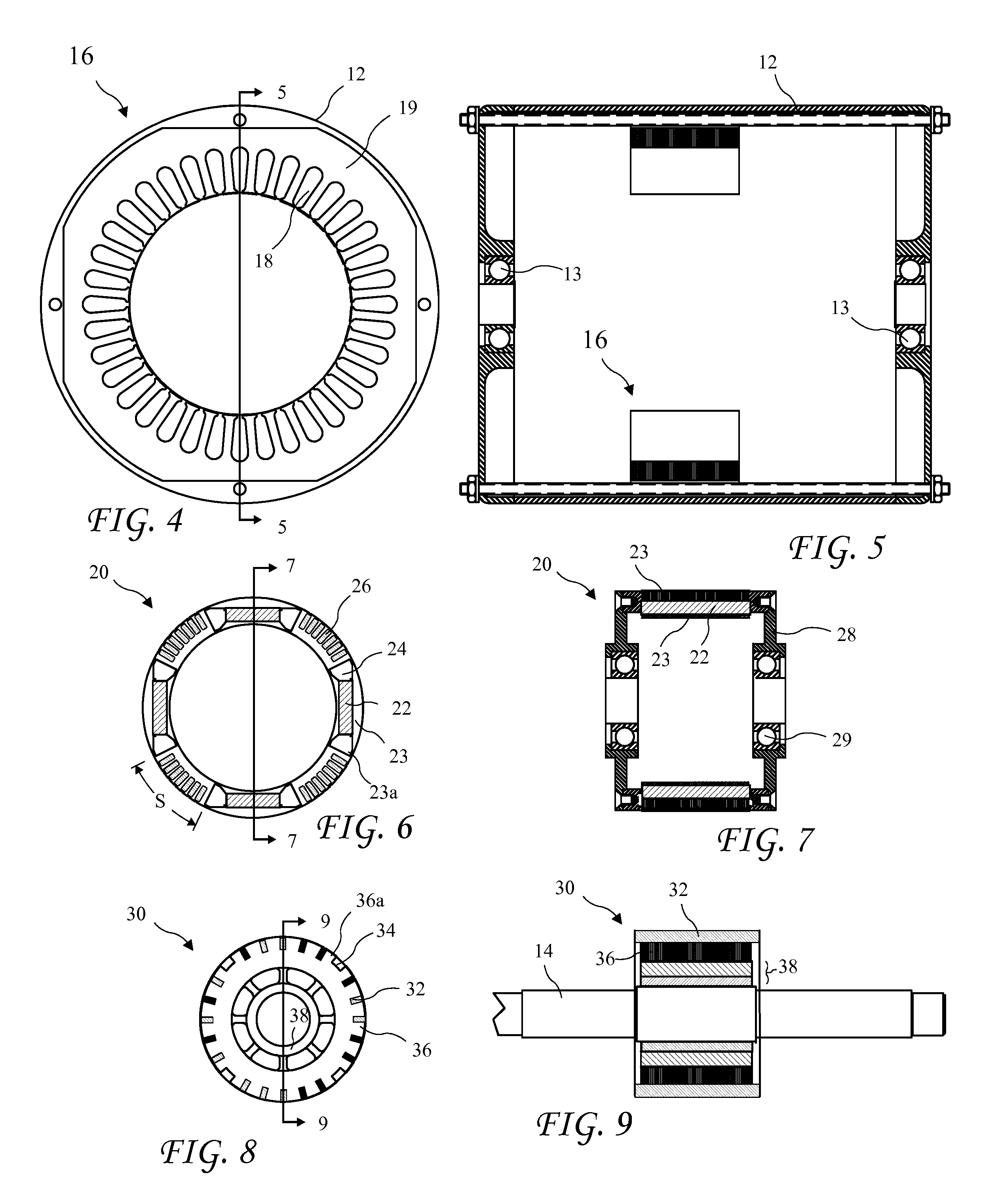
[0025]An end view of an electric motor 10 having an independently rotating Hybrid Permanent Magnet / squirrel Cage (HPMSC) outer rotor 20 and a Squirrel Cage (SC) inner rotor 20 fixedly coupled to a motor shaft 14, according to the present invention is shown in FIG. 1A, and a side view of the electric motor 10 is shown in FIG. 1B. A cross-sectional view of the electric motor 10 taken along line 2-2 of FIG. 1B, is shown in FIG. 2, and a cross-sectional view of the electric motor 10 taken along line 3-3 of FIG. 1A is shown in FIG. 3. The electric motor 10 includes a housing 12, a stator portion 16 fixedly coupled to the housing 12, the independently r...


PUM


Abstract

A hybrid induction motor includes a fixed stator, an independently rotating HPMSC outer rotor, and a Squirrel Cage (SC) inner rotor fixed to a motor shaft. The HPMSC rotor has spaced part permanent magnets and sets of first bars between consecutive permanent magnets. The SC rotor has groups of second bars, and slots in an outer surface between consecutive groups of the second bars. The HPMSC rotor is initially accelerated by cooperation of the stator with the first bars. The permanent magnets create a rotating magnetic field cooperating with the second bars to accelerate the SC rotor. As the HPMSC rotor accelerates towards synchronous RPM, the stator field reaches into the HPMSC rotor and cooperates with the permanent magnets to transition to synchronous operation. Salient poles created by cooperation of the permanent magnets with the slots lock the two rotors at synchronous RPM.

Description

BACKGROUND OF THE INVENTION[0001]The present invention relates to electric motors and in particular to an induction motor having an independently rotating permanent magnet rotor variably coupled to an inductive rotor to reconfigure the motor from asynchronous induction operation at startup to synchronous operation after startup for efficient operation.[0002]A preferred form of electric motors are brushless AC induction motors. The rotors of induction motors include a cage (or squirrel cage resembling a “hamster wheel”) rotating inside a stator. The cage comprises axially running bars angularly spaced apart on the outer perimeter of the rotor. An AC current provided to the stator introduces a rotating stator magnetic field inside the rotor, and the rotating field inductively induces current in the bars. The current induced in the bars creates an induced magnetic field which cooperates with the stator magnetic field to produce torque and thus rotation of the rotor.[0003]The introducti...

Claims


Application Information

Patent Timeline
Patent Type & Authority Applications(United States)
IPC IPC(8): H02K16/02H02K1/22H02K21/46
CPCH02K16/025H02K1/223H02K21/46H02K16/02H02K17/26H02K1/2791H02K1/276H02K1/27H02K1/2706H02K1/22H02K1/28H02K16/00
Inventor FINKLE, LOUIS J.
Owner MOTOR GENERATOR TECH INC
Learn More